background image

TABLE OF CONTENTS

SECTION 1 —  GENERAL INFORMATION . . . . . . . . . . . . . . . . . . . . . . . . . . . . . . . . . . . . . . . - 1 -

1.1

INTRODUCTION . . . . . . . . . . . . . . . . . . . . . . . . . . . . . . . . . . . . . . . . . . . . . . . . . - 1 -

1.2

BENEFITS . . . . . . . . . . . . . . . . . . . . . . . . . . . . . . . . . . . . . . . . . . . . . . . . . . . . . . . - 1 -

1.3

USES . . . . . . . . . . . . . . . . . . . . . . . . . . . . . . . . . . . . . . . . . . . . . . . . . . . . . . . . . . . - 2 -

1.4

PRINCIPLE OF OPERATION . . . . . . . . . . . . . . . . . . . . . . . . . . . . . . . . . . . . . . . - 2 -

1.5

TECHNICAL SPECIFICATIONS . . . . . . . . . . . . . . . . . . . . . . . . . . . . . . . . . . . . . - 3 -

1.6

PRECAUTIONS . . . . . . . . . . . . . . . . . . . . . . . . . . . . . . . . . . . . . . . . . . . . . . . . . . - 4 -

SECTION 2  —  INSTALLATION . . . . . . . . . . . . . . . . . . . . . . . . . . . . . . . . . . . . . . . . . . . . . . . . - 5 -

2.1

SYSTEM CONFIGURATION . . . . . . . . . . . . . . . . . . . . . . . . . . . . . . . . . . . . . . . - 5 -

2.2

RheoVac


SENTRY

 INSTALLATION/SITE SELECTION . . . . . . . . . . . . . . . . . . - 5 -

2.2.1

Probe Site Selection . . . . . . . . . . . . . . . . . . . . . . . . . . . . . . . . . . . . . . . . . . - 5 -

2.2.2

CPU/Distribution Box Site Selections . . . . . . . . . . . . . . . . . . . . . . . . . . . . - 6 -

2.3

HOT TAP INSTALLATION . . . . . . . . . . . . . . . . . . . . . . . . . . . . . . . . . . . . . . . . . - 7 -

2.4

PROBE INSTALLATION . . . . . . . . . . . . . . . . . . . . . . . . . . . . . . . . . . . . . . . . . . . - 7 -

2.5

ELECTRICAL CONNECTIONS . . . . . . . . . . . . . . . . . . . . . . . . . . . . . . . . . . . . . - 9 -

SECTION 3  —  OPERATION . . . . . . . . . . . . . . . . . . . . . . . . . . . . . . . . . . . . . . . . . . . . . . . . . . - 13 -

3.1

GENERAL INFORMATION . . . . . . . . . . . . . . . . . . . . . . . . . . . . . . . . . . . . . . . - 13 -

3.2

OUTPUT PARAMETERS . . . . . . . . . . . . . . . . . . . . . . . . . . . . . . . . . . . . . . . . . - 13 -

3.3

RheoVac


SENTRY

 PROBES . . . . . . . . . . . . . . . . . . . . . . . . . . . . . . . . . . . . . . . . - 13 -

3.4

CPU TOUCH SCREEN . . . . . . . . . . . . . . . . . . . . . . . . . . . . . . . . . . . . . . . . . . . . - 14 -

3.5

ETHERNET or MODEM OUTPUT . . . . . . . . . . . . . . . . . . . . . . . . . . . . . . . . . . - 18 -

3.6

SEARCHING FOR LEAKS WITH MULTI-PROBE SYSTEM . . . . . . . . . . . . - 20 -

SECTION 4  —  MAINTENANCE . . . . . . . . . . . . . . . . . . . . . . . . . . . . . . . . . . . . . . . . . . . . . . . - 22 -

4.1

GENERAL MAINTENANCE . . . . . . . . . . . . . . . . . . . . . . . . . . . . . . . . . . . . . . . - 22 -

4.2

CALIBRATION . . . . . . . . . . . . . . . . . . . . . . . . . . . . . . . . . . . . . . . . . . . . . . . . . . - 22 -

4.3

SPARE PARTS . . . . . . . . . . . . . . . . . . . . . . . . . . . . . . . . . . . . . . . . . . . . . . . . . . - 22 -

4.4

TROUBLE SHOOTING . . . . . . . . . . . . . . . . . . . . . . . . . . . . . . . . . . . . . . . . . . . - 22 -

SECTION 5  —  CUSTOMER SERVICE . . . . . . . . . . . . . . . . . . . . . . . . . . . . . . . . . . . . . . . . . - 24 -

5.1

QUESTION ON EXISTING HARDWARE . . . . . . . . . . . . . . . . . . . . . . . . . . . . - 24 -

5.2

TROUBLE SHOOTING . . . . . . . . . . . . . . . . . . . . . . . . . . . . . . . . . . . . . . . . . . . - 24 -

5.3

FACTORY AND FIELD SERVICE . . . . . . . . . . . . . . . . . . . . . . . . . . . . . . . . . . - 24 -

5.4

QUESTIONS ON NEW EQUIPMENT . . . . . . . . . . . . . . . . . . . . . . . . . . . . . . . . - 24 -

SECTION 6  —  CUSTOM INFORMATION . . . . . . . . . . . . . . . . . . . . . . . . . . . . . . . . . . . . . . - 25 -

6.1

UNIT IDENTIFICATION . . . . . . . . . . . . . . . . . . . . . . . . . . . . . . . . . . . . . . . . . . - 25 -

6.2

CONFIGURATION . . . . . . . . . . . . . . . . . . . . . . . . . . . . . . . . . . . . . . . . . . . . . . . - 25 -

6.3

SPECIAL INSTRUCTIONS . . . . . . . . . . . . . . . . . . . . . . . . . . . . . . . . . . . . . . . . - 25 -

©Intek, Inc. 2004

Manual no. RV

Sentry

 Rev. A

I:\OFFICE\WPMAN UAL\SENTRY\RVSentryRev. A.wpd

Содержание RheoVac

Страница 1: ... 3 1 GENERAL INFORMATION 13 3 2 OUTPUT PARAMETERS 13 3 3 RheoVac SENTRY PROBES 13 3 4 CPU TOUCH SCREEN 14 3 5 ETHERNET or MODEM OUTPUT 18 3 6 SEARCHING FOR LEAKS WITH MULTI PROBE SYSTEM 20 SECTION 4 MAINTENANCE 22 4 1 GENERAL MAINTENANCE 22 4 2 CALIBRATION 22 4 3 SPARE PARTS 22 4 4 TROUBLE SHOOTING 22 SECTION 5 CUSTOMER SERVICE 24 5 1 QUESTION ON EXISTING HARDWARE 24 5 2 TROUBLE SHOOTING 24 5 3 FA...

Страница 2: ...n thus defective this warrantybeing expresslyin lieu of all other warranties express or implied and all other obligation or liabilities on Intek s part The purchaser will assume all responsibility and expense for removal decontamination and reinstallation of equipment Intek s instruments are manufactured under United States patent numbers 4 255 968 4 942 763 4 949 578 5 445 018 5 485 754 and 5 752...

Страница 3: ...ir in leakage the SENTRY System provides valuable information that can be used to analyze problems associated with vacuum system components thereby improving plant efficiency reducing downtime and increasing maintenance effectiveness 1 2 BENEFITS The following are some of the unique benefits of the RheoVac SENTRY System Distinguishes between air flow and water vapor flow Measures exhauster capacit...

Страница 4: ...es multiple primary sensors configured in a single probe head and an electronic signal conditioner and digital signal processor unit The sensing probe is installed in the vacuum line between the condenser and the exhauster The RheoVac instrument makes no assumptions about the dynamic condenser and vacuum line environment The sensor head employs the patented Rheotherm technology to provide an accur...

Страница 5: ...vacuum line No field adjustments are required In the RheoVac SENTRY System multiple RheoVac probes are installed at pre determined condenser vacuum line locations to provide the most appropriate measurement data for the condenser system Dependingon theplantconfiguration sometimesasingleSENTRY Systemcan be configured to monitor more than one generating unit The probes are connected to the SENTRY CP...

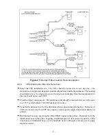
Страница 6: ... are vital to achieving optimal performance from the RheoVac system See Figure 2 Use reasonable care in handling the sensing probe s the sensing components are delicate Take care not to bend the probes damage the tips or otherwise obstruct the sensing ports When a probe is taken out of line always place it in the protective sheath which is shipped with probes from the factory Use proper input powe...

Страница 7: ...nd select the most preferred location that fits your vacuum line configuration DO NOT INSTALL THE PROBE DOWNSTREAM OF ANY TRAP SECTIONS AS SHOWN IN FIGURE 2 CONFIGURATIONS B AND D Special installation instructions unique to your unit where applicable will be noted in SECTION 6 3 SPECIAL INSTRUCTIONS Refer to this section now to review any special instructions Check installation clearance The probe...

Страница 8: ...put voltageaccess The electronics unit should be located in an area with access to a 115 Vac single phase 50 60 Hz input power source Consider the distances to all of the distribution boxes located near the probes Distances of 250 feet or more away from CPU mayrequire a remote power supply depends on number of probes Distribution boxes are used to split off the RS485 signal to the probes Distances...

Страница 9: ...ll probe to same location Custom labeling of the SENTRY screen with probe serial numbers or other I D is possible see Section 3 3 Ð Verify stop clamp location see Figure 3 A stop clamp is attached to each probe as an indication of its insertion depth It is important this stay in place in order for the probe to be installed correctly and to ensure the end of the probe does not contact the opposing ...

Страница 10: ... 8 Probe Installation Detail ...

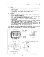
Страница 11: ...t between the distribution enclosure and the probes unless rigid conduit is used for long distance runs c The probe connector has an adapter which allows the attachment of the flexible conduit connector d Connect the probes to the distribution enclosure using the manufacturer supplied four conductor shielded cable Probe cable connections are shown in Figure 5 e A termination resistor is required i...

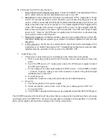
Страница 12: ...touch screen display This connection is via an RJ45 plug using CAT 5 straight Ethernet high noise immune cable installed from the customer s LAN system to the SENTRY CPU C Initial Power Up 1 Verify power connections to prevent damage to the electronics in the probes a Prior to powering up the system for the first time remove the connector from each probe b Leave the UPS power off Apply power only ...

Страница 13: ... 11 Figure 6 CPU Wiring Part 1 ...

Страница 14: ... 12 Figure 7 CPU Wiring Part 2 ...

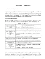
Страница 15: ...is not a measure of air in leak It is a measure of steam jet air ejector capacity WATER VAPOR MASS FLOW lbs hr The water vapor component of the flowing gas being removed from the condenser RheoVac PRESSURE Hg Absolute pressure at the RheoVac probe head Should be equal to or less than turbine back pressure WATER VAPOR SPECIFIC VOLUME cu ft lb The inverse density of the water vapor present in the li...

Страница 16: ...our plant mayhave the SENTRY CPU monitoring probes installed on more than one generating unit Accordingly it is imperative that the serial number of the probes and their installed locations as shown on the original factory configuration be clearly retained and readily accessible 3 4 CPU TOUCH SCREEN The RheoVac SENTRY System CPU touch screen provides operator access interfaceand control of the com...

Страница 17: ... Temperature see bottom left for parameter selection and the data for that parameter from all the probes in the system will be displayed The data is shown as a graph in the top half of the screen and in measured values in the bottom half of the screen The data is color keyed for each probe For the graph display the y axis minimum and maximum values are controlled by the buttons on the left side of...

Страница 18: ...Tool The Diagnostic Tool button leads to the display screen shown in Figure 11 While this illustrative display only shows the data for two probes the actual screen will show the data from all probes in the SENTRY System The data for each probe is displayedon two lines the top line ...

Страница 19: ...w much space is used by the data stored in the CPU and the amount of free space available for storing additional data on the system s hard drive Generally it will not be necessary to removestored system data to archive files in order to make room on the hard drive Viewing this information aids the plant in determining a suitable archive schedule Recal Repair This selection on the main RheoVac SENT...

Страница 20: ... RheoVac data 99261 5 091400 dat Note that the filename will always be six characters plus the file extension Two digits each are used for the month day and year If you are accessing the data files from a remote location via Ethernet or modem connection the above file path would be modified to the following computer_name c RheoVac data 99261 5 091400 dat where computer_name is the Network Identifi...

Страница 21: ...ial Pressure Actual Volume Flow Relative Saturation Water Vapor Specific Volume Water Air Mass Ratio and Temperature This data is arranged in a table as shown in Figure 15 so that the NetDDE clientcan request information from each cell of the table using the provided NetDDE Service Name Topic Name and the corresponding row and column as the NetDDE Item Name ...

Страница 22: ...n Additionally the RheoVac system provides recordable real time air in leak measurements and will respond to changes of air in leak flow within 1 minute Therefore it can be used to quantifyeach source of air in leakage as repairs are made Examination of the measured air in leak datafrom the installed probes will provide information on the likely location s of the leaks which give rise to the measu...

Страница 23: ...ata and corresponding identification of leak presence and leak location determinations are Leak Location Probe Indications of Air In Leak SCFM Normal tight system 1 2 5 SCFM 2 2 5 SCFM 3 5 SCFM 4 0 SCFM exhauster 2 not in service 5 5 SCFM Abnormal need to locate and fix leaks central joint seal 1 15 SCFM 2 18 SCFM 3 33 SCFM 4 16 5 SCFM 5 16 5 SCFM Abnormal need to locate leaks and fix Nash pump sh...

Страница 24: ...ve year period Should the unit require re ranging or recalibration note the serial number of the RheoVac instrument and contact the factory concerning recalibration cost and turn around times Refer to SECTION 5 CUSTOMER SERVICE of this manual for additional information 4 3 SPARE PARTS There are no normallyrecommended spare components to stock However it is desirable and usually cost effective to o...

Страница 25: ...e 1 Remove sensor from flow stream and contact factory 2 Contact factory Wet probe 1 This usually indicates a condenser design or operation problem that requires corrective action 1 Contact factory RS sensor problem 1 RS sensor or circuit has failed 1 Contact factory Mass flow output saturates high will not respond to flow changes 1 Flow rate is not within range of calibration 2 Blown heater fuse ...

Страница 26: ...our experienced engineers for assistance 5 3 FACTORY AND FIELD SERVICE If you request fieldservice Intek has experienced engineersavailable to meet your needs TheRheoVac instrument is complex and most repairs or re calibrations will require returning the instrument to the factory If a problem cannot be solved over the phone with your help we will determine if factory service or field service will ...

Страница 27: ...entification Pipe size probe serial no assigned location identification Pipe size probe serial no assigned location identification Pipe size probe serial no assigned location identification Pipe size probe serial no assigned location identification Pipe size probe serial no assigned location identification Pipe size probe serial no assigned location identification Pipe size probe serial no assigne...

Отзывы: