background image

11

Connections

REMOTE 

CONTROL

FM

75

AM

ANTENNA

GND

L

R

CENTER

SUB

WOOFER

FRONT

SURR

SUBWOOFER

OPTICAL

COAXIAL

1

2

1

2

PRE OUT

MULTI

CHANNEL INPUT

DIGITAL INPUT

L

R

OUT

IN

PHONO

TAPE

CD

IN

OUT

IN

IN

12 V

TRIGGER

MONITOR

OUT 

DVD

VIDEO

VIDEO 1

L (White)

R (Red)

L (White)

R (Red)

3. Tape deck, MD recorder, 

DAT deck,  CD recorder, 
(TAPE)

Analog audio input

Analog audio output

1. Turntable

(PHONO)

Analog audio output

Ground wire (earth)

L (White)

R (Red)

2. CD player

 (CD)

Analog audio output

Digital audio output (optical)

L (White)

R (Red)

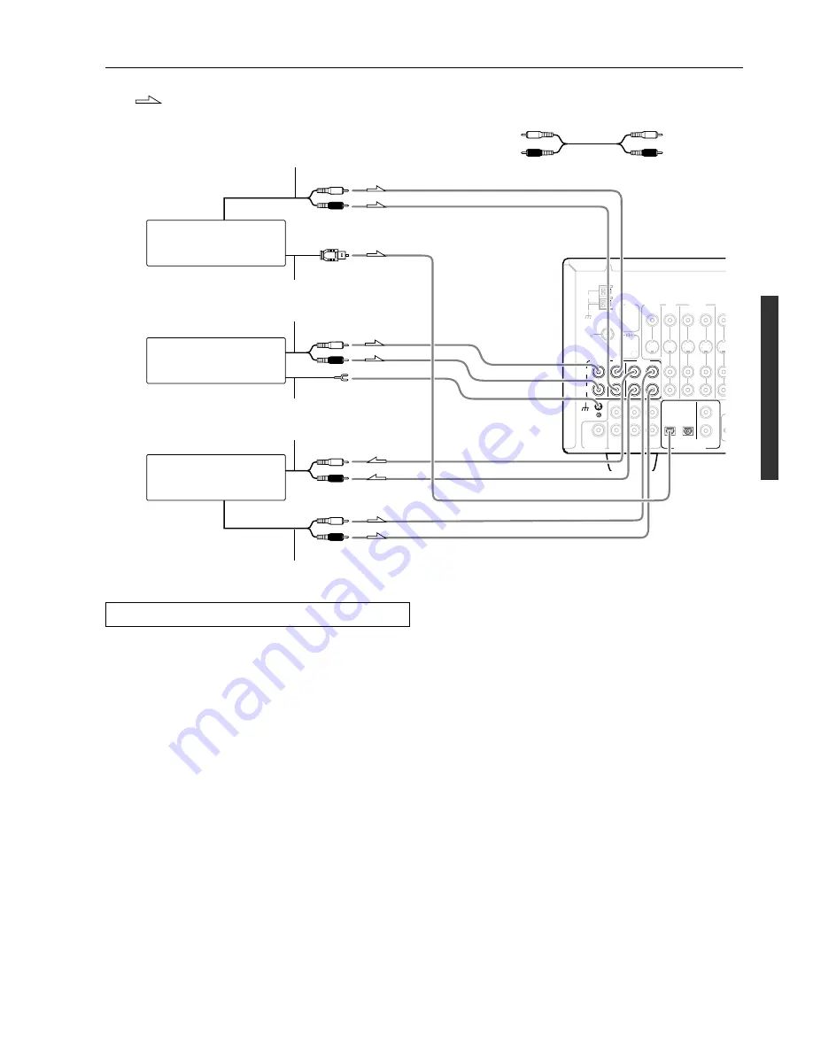
Connecting your audio components

Below is an example of how you can connect your audio
components to the DTR-5.2. Refer to the diagram above for the
following connection examples.

1. Connecting a turntable (PHONO)

Using an RCA-type audio connection cable, connect the output
terminal on the turntable to the PHONO input jacks on the DTR-5.2.
Make sure that you properly connect the left channel to the L jack
and the right channel to the R jack.

Note:

The DTR-5.2 is designed for use with moving magnet cartridges.
For proper operation, connect a ground (or earth) wire to the GND
terminal. For some turntables, however, connecting the ground wire
may cause increased noise, and in such a case, a ground wire is not
necessary and should not be connected.

2. Connecting a compact disc player (CD)

Using an RCA-type audio connection cable, connect the output
terminal on the compact disc player to the CD input jacks on the
DTR-5.2. Make sure that you properly connect the left channel to the
L jack and the right channel to the R jack.

If the compact disc player has a digital output jack as well, be sure to
also connect it to either a DIGITAL INPUT (COAXIAL) or
DIGITAL INPUT (OPTICAL) jack on the DTR-5.2 depending on
the type of connector on the compact disc player.

With the initial settings of the DTR-5.2, the CD input source is
set for digital input at the OPTICAL 1 jack.

If the digital connection is made at a different jack, this must be
changed at the setup menu: Input Setup 

 Audio Setup 

→ 

Digital

Input (see page 29).

3. Connecting a cassette tape deck, MD recorder, DAT

deck, or CD recorder (TAPE)

Using an RCA-type audio connection cable, connect the output
terminals (PLAY) of the device to the TAPE IN jacks on the DTR-
5.2 and the input terminals (REC) to the TAPE OUT jacks. Make
sure that you properly connect the left channel to the L jack and the
right channel to the R jack.

If the device has a digital output jack as well, be sure to also connect
it to either a DIGITAL INPUT (COAXIAL) or DIGITAL INPUT
(OPTICAL) jack on the DTR-5.2 depending on the type of
connector on the device.

With the initial settings of the DTR-5.2, the TAPE input source
is set for no digital input.

If you connect the device to the DIGITAL INPUT terminal, then this
input source must be set for digital input at the setup menu: Input
Setup 

 Audio Setup 

 Digital Input (see page 29).

Audio connection cable

: Signal flow

Left (White)

Right (Red)

L

R

Содержание DTR-5.2

Страница 1: ...remote controller 40 Programming the commands of remote controllers for other devices into the remote controller 42 Using a Macro function 45 Setup and operation Speaker setup 21 Listening to Radio Br...

Страница 2: ...uilt up static charges Article 810 of the National Electrical Code ANSI NFPA 70 provides in formation with regard to proper grounding of the mast and sup porting structure grounding of the lead in wir...

Страница 3: ...ns may cause harmful interference to radio communications However there is no guarantee that interference will not occur in a particular installa tion If this equipment does cause harmful interference...

Страница 4: ...R IN OUT Terminals 40 FM AM random presets IntelliVolume Powerful backlit programmed learning remote with macros and mode key LEDs Manufactured under license from Dolby Laboratories Dolby Pro Logic an...

Страница 5: ...ut this will vary depending on usage 3 2 1 30 30 Using the remote controller Point the remote controller toward the remote control sensor The STANDBY indicator lights up when the unit receives a signa...

Страница 6: ...LEEP MEMORY SPEAKERS FM MUTE PCM DIGITAL TUNED FM STEREO dB STEREO A B MPEG DTS Front panel facilities See illustration below Here is an explanation of the controls and displays on the front panel of...

Страница 7: ...ctive only for the front left and right speakers and headphones Front display Remote control sensor 5 Phones Smart Scan Navigator jog dial and indicators 21 22 24 27 29 32 Used to make settings in the...

Страница 8: ...is in RETURN button 21 22 29 32 Press to move up one level in the setup mode CH DISC button 35 36 When in the RCVR mode for selecting a tuner preset channel For selecting the disc to be played back fo...

Страница 9: ...in the home environment On Select to turn on the re equalization filter Off Select to turn off the re equalization filter Note The Re EQ function is effective on the Dolby Pro Logic II Movie and Dolb...

Страница 10: ...ptical input jacks remove the protective cap and keep it safely When the jack is not used replace the protective cap When using an optical input jack always use an optical fiber cable Optical digital...

Страница 11: ...terminal on the compact disc player to the CD input jacks on the DTR 5 2 Make sure that you properly connect the left channel to the L jack and the right channel to the R jack If the compact disc play...

Страница 12: ...corder is equipped with an S video output terminal connect it to the S VIDEO 1 IN terminal with an S video cable If it does not have an S video output terminal connect its video output terminal to the...

Страница 13: ...set for digital input at the setup menu Input Setup Audio Setup Digital Input see page 29 7 Connecting a television monitor or projector MONITOR OUT If the monitor or projector is equipped with an S...

Страница 14: ...ower on ready function When the DTR 5 2 is in the standby state if an z connected component is turned on then the DTR 5 2 also turns on and the input source selected at the DTR 5 2 automatically switc...

Страница 15: ...ntroller to reach If the remote controller signal does not reach other components In this situation you will need to use a commercially available IR emitter Connect the IR emitter to the IR OUT termin...

Страница 16: ...or subwoofer is not connected the sound from the unused channel is properly distributed to the connected speakers in order to produce the best Surround sound possible Front The left right and center s...

Страница 17: ...MS MIN SPEAKER IMPEDANCE SELECTOR SET BEFORE POWER ON 4 or above speaker 6 or above speaker NO R L R L Be sure to connect the positive and negative cables for the speakers properly If they are mixed u...

Страница 18: ...witch to set the DTR 5 2 to standby state The Standby indicator will light up 3 Press the Standby On button to turn on the DTR 5 2 The display and four jog dial indicators will light up and the Standb...

Страница 19: ...antenna is for indoor use only Set it in the direction and position where you receive the clearest sound Put it as far away as possible from the DTR 5 2 televisions speaker cables and power cords When...

Страница 20: ...V or VCR reception since the FM and TV or VCR signals can interfere with each other If you must use a common FM TV or VCR antenna use a directional linkage type splitter Connecting an FM outdoor anten...

Страница 21: ...tton on the remote controller once 2 Press the jog dial or ENTER button on the remote controller Speaker Configuration These settings tell the DTR 5 2 which speakers you have connected and what size t...

Страница 22: ...speaker At this point it is not necessary to adjust the volume of the test sound 2 Press the jog dial or the ENTER button on the remote controller FEET Select if you will enter the distances in feet M...

Страница 23: ...ource button 2 Using the Tuning and buttons on the front panel tune into the station you desire The tuner frequency changes in 50 kHz increments for FM and 10 kHz increments for AM When tuning into FM...

Страница 24: ...Video 1 Video 3 Bass Treble Master Volume Smart Scan Navigator Dimmer Display Tuning FM Mode Preset Memory Preset VCR Audio Selector Tape FM AM Phono CD Push To Enter DSP Mode ADJ Setup Return CH Leve...

Страница 25: ...ftware the listening mode will automatically change to Dolby Digital or DTS With Dolby Digital and Dolby Pro Logic II Movie you can use the Re EQ function for more details see page 9 Tip You can set i...

Страница 26: ...peakers B When using the B speakers the A speakers can only be used for stereo or direct playback so nothing will be output from the left and right surround speakers during multichannel playback Adjus...

Страница 27: ...the tone using the Bass and Treble dials Bass Treble DIRECT 2 Push To Enter DSP Mode ADJ When using the remote controller 1 Press the RCVR MODE button 2 Press the CH SEL button and select the desired...

Страница 28: ...nnels left and right front center and two surround channels plus an LFE channel Low Frequency Effect for the low range effect sound It will create a realistic sound that can be heard in the theaters a...

Страница 29: ...lt settings given in the table below then there is no need to change this setting Multichannel MULTICH This setting will not appear if AM or FM is selected at the front panel for the input source The...

Страница 30: ...ut Setup FM AM Phono CD Tape VCR DVD Video 3 Video 2 Video 1 1 Select the desired input source Push To Enter DSP Mode ADJ Push To Enter DSP Mode ADJ DTR 5 2 Remote controller Push To Enter DSP Mode AD...

Страница 31: ...ected to the 12V TRIGGER terminal when the input source is selected OFF Select when no device is connected to the 12V TRIGGER terminal or you do not want the connected device to activate 1 Select the...

Страница 32: ...urn the jog dial or press the and cursor buttons on the remote controller to display 3 PREFERENCE 2 Press the jog dial or ENTER button on the remote controller Turn the jog dial or press the cursor bu...

Страница 33: ...ord the source connected to the MULTI CHANNEL INPUT connector FM AM Phono CD Tape VCR DVD Video 3 Video 2 Video 1 3 Set the tape deck in recording mode Start playing the source Set the proper recordin...

Страница 34: ...utton to select the desired preset station number Controlling an Integra Onkyo cassette tape deck The z connector of the Integra Onkyo cassette tape deck must be connected to the DTR 5 2 see page 14 1...

Страница 35: ...ion buttons that can be used to control an Integra Onkyo compact disc player Operation buttons ON Turns on and off the compact disc player same as STDBY button on the remote controller DISC Selects a...

Страница 36: ...ENU or MENU Displays the menu screen s recorded on DVD media DISC Selects a disc in the DVD changer AUDIO A Press repeatedly to select an audio and or language track recorded on a DVD Audio Video ANGL...

Страница 37: ...may also use the following buttons VOL Adjusts the volume at the DTR 5 2 MUTING Activates the muting function at the DTR 5 2 MD operation buttons Numeric keys Using remote controller SAT CABLE VCR an...

Страница 38: ...ve If it still does not operate properly then program the commands one by one to the buttons on the RC 441M remote controller When entering the code of Integra Onkyo DVD players There are three SETTIN...

Страница 39: ...MIVAR 174 175 NEC 176 177 NOKIA 178 179 180 181 OCEANIC 181 NORDMENDE 182 183 OKANO 152 ORION 184 185 186 PANASONIC 187 188 189 190 PHILIPS 152 162 191 PIONEER 192 193 PROSCAN 194 QUASAR 195 RADIO SHA...

Страница 40: ...ss the SAT MODE button The SAT button lights green 2 Press the desired operation button The buttons shaded in the figure to the left are the operation buttons that can be used to control your satellit...

Страница 41: ...n the television channels TV VCR Switches the TV VCR input for the television 0 1 to 9 10 Numeric keys ENTER Confirm VOL Adjusts the volume at the television MUTING Activates the muting function at th...

Страница 42: ...er over to the RC 441M remote controller one at a time Each command is then programmed to a different button on the RC 441M remote controller Any button is programmable for this step except for the ei...

Страница 43: ...ee times quickly and the remote controller exits the programming mode Resume from Step 2 If a failure occurs during programming the SEND LEARN indicator flashes three times quickly and the remote cont...

Страница 44: ...the SEND LEARN indicator flashes three times quickly and the remote controller exits the erasing mode Resume from Step 1 Erasing all the commands programmed under a MODE button 1 Press and hold down...

Страница 45: ...te controller exits the programming mode Resume from Step 1 Running a Macro function Perform the procedure below to run a macro function that you have programmed into the remote controller After progr...

Страница 46: ...during the programming the SEND LEARN indicator flashes three times quickly and the remote controller exits the programming mode Resume from Step 1 If you perform an invalid operation during programm...

Страница 47: ...writing the previous macro with a new macro Erasing a direct macro from the DIRECT MACRO button 1 Press and hold down any one of the eight MODE buttons press the DIRECT MACRO button and then release b...

Страница 48: ...LEARN indicator lights up for about ten seconds and then turns off All programmed commands and macros are erased and the remote controller returns to its factory presets Notes Proceed to Step 3 immedi...

Страница 49: ...dB Tone Control Bass 10 dB at 50 Hz Treble 10 dB at 20 kHz Signal to Noise Ratio Stereo Phono 80 dB IHF A 5 mV input CD Tape 100 dB IHF A 0 5 V input Muting 50 dB TUNER SECTION FM Tuning Range 87 5 to...

Страница 50: ...age 21 Subwoofer speakers output level setting is improper Check the output level of the Subwoofer using the test tone page 22 Low frequency humming is heard Not properly grounded Check outer conducto...

Страница 51: ...layback source is not Dolby Digital encoded Check that the DOLBY DIGITAL indicator lights up on the display Re EQ function cannot be used Re EQ is only enabled for Analog PCM sources and Dolby Digital...

Страница 52: ...Way Upper Saddle River N J 07458 U S A Tel 201 785 2600 Fax 201 785 2650 E mail integra onkyousa com Integra Division of ONKYO CORPORATION Sales Product Planning Div 2 1 Nisshin cho Neyagawa shi OSAKA...

Отзывы: