


Customer Services (858) 578-7887 & (888) GO IN
TEC
IN
TEC
Controls, 12700 Stowe Dr., Suite 1
0
0, Poway, CA 92064
Fax (858) 578-4633 & (888) FX IN
TEC
www.inteccontrols.com
Specification subject to change without notice.
Printed in USA 131119
Polygard® is a registered trademark of MSR
MGC2-16
PolyGard
®
Multi-Point Controller
User Manual - MGC2-16
Page 25
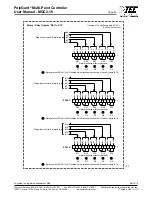
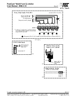
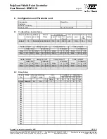
4.2 Unit position – Connection diagram
ill. 1
H N
Gray
Blue
Green/Y
ellow
AC hot
AC neutral
Earth ground
Terminal block
120 VAC Input Power Supply
• “Min wire size 16 AWG (1.5 mm
2
)”
• Resettable breaker, max 10 A,
rated current approx. 2 A
120 VAC (90...230 VAC), 50/60 Hz
G
(see ill. 4)
(see ill. 3)
H
Gray
N
Blue
G
Green/Ye
G
Green/Ye
X
Gray
Binary - Relay Outputs
(see ill. 1)
120 VAC
Input Power
1
X10
X11
X2
2
2 3 4 5 6
7 8 9 10 11 12 13 14 15
1
1 2 3 4 5 6 7 8 9 101112
1 2 3 4 5 6 7 8 9 101112
X1
Binary - Relay Outputs
R11
R13
R12
R14 R15
(see ill. 2)
1
X10
X11
X2
2
2 3 4 5 6
7 8 9 10 11 12 13 14 15
1
1 2 3 4 5 6 7 8 9 101112
1 2 3 4 5 6 7 8 9 101112
X1
Binary - Relay Outputs
R16
R18
R17
R19 R20
DIN Rail
(see ill. 2)
EP-02-3
EP-02-2
(see ill. 4)
Analog
Outputs
1
X10
X11
X2
2
2 3 4 5 6
7 8 9 10 11 12 13 14 15
1
1 2 3 4 5 6 7 8 9 101112
1 2 3 4 5 6 7 8 9 101112
X1
Binary - Relay Outputs
R06
R08
R07
R09 R10
Sensor
Inputs
(see ill. 2)
(see ill. 3)
(see ill. 6)
EP-02-1
Digital
Inputs
Analog
Outputs
INTEC Controls
05.07 .10 10: 28am
Fault
Fault
Alarm
Alarm
1
X10
X11
X2
2
2 3 4 5 6
7 8 9 10 11 12 13 14 15
1
1 2 3 4 5 6 7 8 9 101112
1 2 3 4 5 6 7 8 9 101112
X1
R01
R03
R02
R04 R05
Sensor
Inputs
(see ill. 4)
(see ill. 5) (see ill. 6)
Analog
Outputs
Sensor
Inputs
(see ill. 6)
(see ill. 4)
Analog
Outputs
Sensor
Inputs
(see ill. 6)
L
N
G
V-
V+
Power Unit
Top
Bottom
Horn
Circuit breaker
1F1
Output
24 VDC
1
2
Terminal
block “X1”
DIN Rail
(see ill. 2)
Optional:
Modbus Interface
(see ill. 8)
(see ill. 7)
(+)(-)(A)(B)
C5 Comm.
Coupler
Optional:
BACnet
X2
X1
3 4 5 6 7 8
1 2 3 4
1 2


