background image

Customer Services (858) 578-7887 & (888) GO IN

TEC

IN

TEC

 Controls, 12700 Stowe Dr., Suite 1

0

0, Poway, CA 92064

Fax (858) 578-4633 & (888) FX IN

TEC

www.inteccontrols.com

Specification subject to change without notice.

Printed in USA 131119

Polygard® is a registered trademark of MSR

MGC2-16

PolyGard

®

 Multi-Point Controller

User Manual - MGC2-16

Page 21


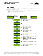
3.7.2  Software Version 


Symbol Description  Default 

Status

Function 

GC02-

XX 

Software 

Version 


XX = Software Version 


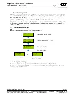
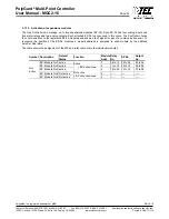
3.7.3  Maintenance Concept 

The  MGC2  system  monitors  the  maintenance  intervals  as  required,  by  local  Regulations  or  Customer 

requirements. 
During startup and/or after maintenance the date for next maintenance is entered. When this date is reached at 9 

o'clock  the  next  morning  a  failure  signal  is  activated  and  Start  Menu  displays  the  phone  No.  of  the  service 

company.  The  failure  signal  (maintenance)  can  be  acknowledged  by  the  operator.  The  maintenance  message 

(Service Phone No.) is reset after maintenance is accomplished and a new maintenance date is entered. 
The service phone number can be individually entered in the next menu. 

Symbol Description  Default 

Status

Function 

MM.DD.YY  Maintenance 


MM.DD.YY = Input date for next maintenance. 

8585.... 

Phone No. 


Input the individual service phone No.  


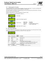
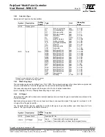
3.7.4  Average Value Function 

The Controller calculates for each active sensing point the arithmetic average value from 10 measurements within 

the time unit defined in this menu “AV-time“. This average value is indicated in the menu “Sensor Readings” near 

the Current Value. During each Sensor Point Setup the control mode of Current Value or Average Value for the 

Stage/Setpoint evaluation is defined.  
The evaluation of the control mode Average Value is overlaid by the Current Value, if this exceeds Stage/Setpoint 

defined in the menu „AV-Overlay”. The overlay is delayed by the time factor set in this menu.  

Symbol Description Default 

Status

Function 

 120 s 

 120pm 

AV- Overlay  120 s 

120 ppm 

sec. = Delay time average value Overlay. 0 = No overlay Function 

ppm = Threshold average Overlay  

1800 s 

AV-Time 

1800 s 

sec. = Time to calculate average value  
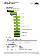
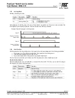
 

3.7.5  Time, Date 

Input and correction of the system time and date. Selection of the time and date format. 

Symbol Description 

Default 

Status 

Function 

US 

Time format  US 

EU = Display time and date in EU format 

US = Display time and date in US format 

hh.mm.ss  Time 


hh.mm.ss = Input the correct time (EU format) 

hh.mm.ss am = Input the correct time (US format) 

MM.DD.YY  Date 


TT.MM.JJ = Input the correct date (EU format) 

MM.DD.YY = Input the correct date (US format)  

Содержание MGC2-16

Страница 1: ...4 Fax 858 578 4633 888 FX INTEC www inteccontrols com Specification subject to change without notice Printed in USA 131119 November 19 2013 Revision Polygard is a registered trademark of MSR MGC2 16 P...

Страница 2: ...Setup 11 3 5 1 Relay Mode 11 3 5 2 Relay Action Steady Flash 11 3 5 3 Latching Mode 12 3 5 4 Horn Function 12 3 5 5 External operation of Relay 13 3 5 6 Delay operation of Relay 13 3 6 Menu SP Setup 1...

Страница 3: ...ademark of MSR MGC2 16 PolyGard Multi Point Controller User Manual MGC2 16 Page 03 5 Start up Operation 29 5 1 Start up 29 5 2 Checklist Start up operation 30 6 Configuration and Parameter card 31 6 1...

Страница 4: ...warn of toxic combustible and refrigerant gases as well as temperature and humidity The Controller MGC2 can measure up to sixteen analog 4 to 20 mA Gas Transmitters Each Sensor Point SP can have five...

Страница 5: ...terface Exits programming and saves settings returns to the previous menu level Enter sub menus stores changed values Scrolls down up in Main menu and Sub menus increases or decreases a value Moves cu...

Страница 6: ...All changes of parameters and staged setpoint values are protected by four digit numeric Code password The code level 1 permits the operation of the MGC2 This code level is intended for the customer...

Страница 7: ...in 5 second intervals Main menu Submenu 1 and 2 Reading and reset of errors See Section 3 1 System Errors Display of the status of actual alarms See Section 3 2 Stage Status Reading and change of the...

Страница 8: ...the relay defined in the system setup as Failure relay is activated The red LED in the front of the Controller flashes During the malfunction of a sensor point SP stages that are assigned for sensor...

Страница 9: ...P 0X Com Error Communication error to expansion module EP 0X Only active if EP module announced Cause EP module address not correct See Start up Operation 5 0 Bus cable to EP 0X module disconnected No...

Страница 10: ...ays can be reset by selecting the Automatic mode The reset of Latching relays also is a function in this menu Select Relay Select Function Manual operation Manual ON Relay ON Select Function Manual OF...

Страница 11: ...3 5 3 Definition of Horn Functions See 3 5 4 Definition of external Relay Operation See 3 5 5 Set Delay ON time See 3 5 6 Set Delay OFF time See 3 5 6 3 5 1 Relay Mode Symbol Description Setting Statu...

Страница 12: ...f Gas Concentration greater smaller as Threshold 3 5 4 Horn Function With this parameter the relay is defined as a horn relay and can be acknowledged with the following possibilities By pressing one o...

Страница 13: ...nal operation of Relay Assign one digital input DI for external setting of the relay ON and or OFF This function has priority before a stage threshold is exceeded and or manual switching in the menu R...

Страница 14: ...each Sensor Point SP Main Menu Selection of a sensor point Activate or deactivate SP See 3 6 1 Define Type See 3 6 2 Define Measuring range See 3 6 3 Define signal type of transmitter See 3 6 4 Define...

Страница 15: ...y OFF time See 3 6 6 Define Control Mode See 3 6 7 Assign a SP Fault to a Stage See 3 6 8 Assign a relay to a Stage See 3 6 9 Assign SP signal to a Analog Output See 3 6 10 3 6 1 Activate Deactivate S...

Страница 16: ...ppm ppm ppm C RH 0 300 0 100 0 50 0 25 0 300 0 25 0 2000 0 100 0 200 0 100 0 20 0 100 0 2000 0 2000 0 2000 0 2000 0 300 0 300 0 300 0 300 0 300 0 300 0 300 0 300 0 300 0 150 0 100 1 Range Recommendati...

Страница 17: ...alue Stage Set point1 Stage 1 Sensor Value Stage Set point1 Stage 2 Sensor Value Stage Set point1 Stage 3 Sensor Value Stage Set point1 Stage 4 Sensor Value Stage Set point1 Stage 5 Sensor Value Stage...

Страница 18: ...ult Status Function SP 01 Sensor Point Selection SP No 1 S1 S2 S3 S4 S5 01 02 03 00 05 01 Stage 1 activate relay R 01 02 Stage 2 activate relay R 02 03 Stage 3 activate relay R 03 00 Stage 4 does not...

Страница 19: ...ntroller User Manual MGC2 16 Page 19 3 7 Menu System Setup Display and change the System Parameters for the Controller Main Menu See 3 7 1 See 3 7 2 See 3 7 3 See 3 7 3 See 3 7 4 See 3 7 4 See 3 7 5 S...

Страница 20: ...3 7 7 See 3 7 7 See 3 7 7 3 7 1 Service Mode If the Service mode is set to ON then the stage setpoints are disabled so relays are not activated during calibration or service work The service mode is R...

Страница 21: ...date for next maintenance 8585 Phone No Input the individual service phone No 3 7 4 Average Value Function The Controller calculates for each active sensing point the arithmetic average value from 10...

Страница 22: ...an be calibrated for 4 and 20 mA using an ampere meter attached with measuring range 25 mA then respective AO factor can be changed to adjust the analog output 4 and or 20 mA During AO calibration no...

Страница 23: ...tached EP 02 is announced in this menu The Controller checks the communication to the registered EP 02 modules and shows a fault signal in case of a communication error To recognize the position of th...

Страница 24: ...should be covered with the enclosed caps after installation Please consider the following when selecting the mounting place Avoid locations where water oil etc may influence proper operation and wher...

Страница 25: ...elay Outputs R11 R13 R12 R14 R15 see ill 2 1 X10 X11 X2 2 2 3 4 5 6 7 8 9 10 11 12 13 14 15 1 1 2 3 4 5 6 7 8 9 101112 1 2 3 4 5 6 7 8 9 101112 X1 Binary Relay Outputs R16 R18 R17 R19 R20 DIN Rail see...

Страница 26: ...on of sensor inputs X10 NO NC COM NO NO NO NO NC NC NC NC COM COM COM COM 5 1 2 4 5 6 7 8 9 11 12 13 14 15 X2 10 3 D1 D2 D3 D4 D5 Stage level control alarming 4 R06 R07 R08 R09 R10 Normal condition fa...

Страница 27: ...EDs D1 to D5 located below terminal connection of sensor inputs X10 Factory pre configured horn and fault fail safe can be reassigned converted for remote control stage level 19 and or 20 NO NC COM NO...

Страница 28: ...Stowe Dr Suite 100 Poway CA 92064 Fax 858 578 4633 888 FX INTEC www inteccontrols com Specification subject to change without notice Printed in USA 131119 Polygard is a registered trademark of MSR MGC...

Страница 29: ...art up the wiring of the Controller including all field devices must be completely terminated After switching the power supply ON and the end of the Power On Time then the Controller is ready for use...

Страница 30: ...ion Password level 1 Customer Password Function analog output Define failure relay Power On Time Service Phone No Maintenance date Parameters Finish Relay R 1 2 3 4 5 6 7 8 9 10 11 12 13 14 15 16 17 1...

Страница 31: ...pass Power On Time Failure Relay ppm Time AV Time Default 15 06 06 06 858 578 7887 120 120 1800 US 1234 30 s 19 Analog output 1 Analog output 2 Analog output 3 Analog output 4 Calibration Calibration...

Страница 32: ...ed trademark of MSR MGC2 16 PolyGard Multi Point Controller User Manual MGC2 16 Page 32 6 3 Sensor Setup SP No SP Status Type Measur ing range SP Signal Stage Setpoints Hyst Delay time sec CV AV Assig...

Страница 33: ...each sensor point Digital inputs Four 4 each can be individually assigned to any relay R1 R20 Digital inputs are used for remote audio visual alarm reset Relay outputs R1 R20 w status LEDs twenty 20 S...

Страница 34: ...L 50 standards color Light gray smoked gray for cover protection NEMA 4X IP65 installation Wall surface mounted Dimensions H x W x D base 16 9 x 12 0 x 5 7 in 430 x 306 x 145 mm Cable entry 10 holes f...

Страница 35: ...2 are installed in compliance with all national and local codes and OSHA requirements Installation should be implemented only by individuals familiar with proper installation techniques and with codes...

Отзывы: