


© INTEC Video Systems, Inc.
Revision F May, 2013
8
Display, Controller and Remote Installation
The display should be mounted where it is easily
viewed and accessible to the driver but not in an
area that may block or impede the drivers and/or
passengers airbags. For a dual drive vehicle, the
display and remote should be placed where they are
accessible from both the left and right side driving
position. (An optional swivel base is available.) The
display should also be mounted in a fashion that
would prevent glare from sunlight affecting the
image seen on the screen. It can also be easily flush
mounted into a cut out in the dash or overhead
console. Generally, overhead center is a good
location, but you should determine what location is
best for your particular installation. Do not obstruct
forward visibility.
Prior to installation, make sure the display does not
block the driver's forward or side view in any way.
1. Locate the area in the cab that best
accommodates the driver and the application. You
will want to make sure the location chosen is
adequate to support the display (a metal surface is
recommended). In cases where the mounting
surface is plastic, support braces may be required.
2. Once you have located the preferred mounting
position, use the mounting bracket supplied with the
display as a template for drilling the holes required
to hold the display in place. When a swivel base is
required, use it as your template. Be sure to verify
that the area being drilled into is clear of all wires
and other items around or underneath so as not to
damage anything.
3. After the holes have been drilled, mount the
bracket with the hardware provided. In some cases,
the hardware provided may not work in your
application. You may need to purchase additional
hardware for your application.
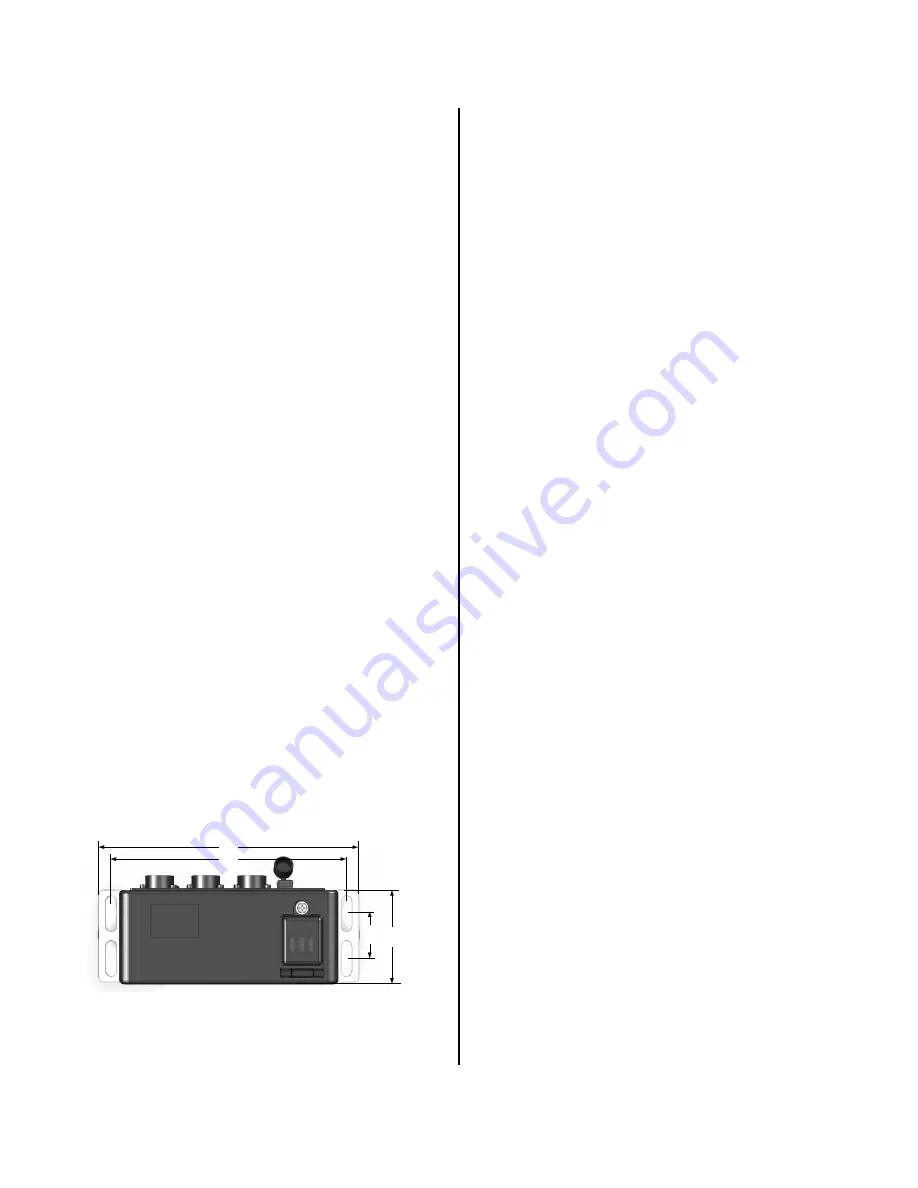
8.27"
7.48"
1.
42
"
3.
36
"
(CVS100XL from the top.)
4. The controller may be installed anywhere within
the cab or outside the vehicle provided you stay
within the available length of the controller to display
cable. (Installation outside requires the CVS100H or
CVS100XL controllers. Do NOT install the CVS100M
outside.) When selecting a location, make sure you
have a solid mounting surface and that the controller
will not come in contact with any of the vehicle’s
electrical circuits as shorting to the controller’s metal
enclosure can occur.
Also be certain to keep the controller and the
controller-to-display cable away from any source of
significant heat (see the Operating Temperature
specs in this manual for the safe operating
temperature range).
5. The controller-to-display cable (CVDC6MA) and
the power harness are provided with the controller.
Install and connect the controller-to-display
cable and the remote control before connecting
the power harness
. The Power (red), Reverse
(blue), and Ground (black) wires on the power
harness need to be connected. The ground wire
should be connected first. To do this, simply locate a
solid chassis ground and secure the wire to it.
Second, should be the power. This should be
connected to a post ig11 to +32 VDC power
source. Finally, connect the reverse wire. It should
be connected to the reverse light circuit or some
other +11 to +32 VDC circuit that is only active when
the vehicle is put into reverse. When connected
properly, this allows the system to come on
automatically and display the OSD distance grid
when the vehicle is placed in reverse.
Mount the remote so that it is easily accessible to
the driver. Please consult your INTEC
Representative with any and all questions regarding
installation.
6. Secure the display in the bracket (with the
mounting knobs provided) and adjust its positioning
as needed.


