17
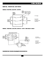
WIRING DIAGRAMS
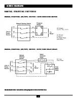
WIRING DIAGRAMS
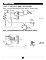
WIRING DIAGRAMS
WIRING DIAGRAMS
WIRING DIAGRAMS
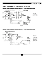
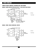
THREE PHASE MANUAL REVERSING SWITCHES
THREE PHASE MANUAL REVERSING SWITCHES
THREE PHASE MANUAL REVERSING SWITCHES
THREE PHASE MANUAL REVERSING SWITCHES
THREE PHASE MANUAL REVERSING SWITCHES
MANUAL THREE PHASE REVERSING SWITCH
MANUAL THREE PHASE REVERSING SWITCH
MANUAL THREE PHASE REVERSING SWITCH
MANUAL THREE PHASE REVERSING SWITCH
MANUAL THREE PHASE REVERSING SWITCH
STANDARD MOTOR CONNECTION WIRING DIAGRAMS
STANDARD MOTOR CONNECTION WIRING DIAGRAMS
STANDARD MOTOR CONNECTION WIRING DIAGRAMS
STANDARD MOTOR CONNECTION WIRING DIAGRAMS
STANDARD MOTOR CONNECTION WIRING DIAGRAMS
NOTE:
NOTE:
NOTE:
NOTE:
NOTE: Do not use this diagram to
connect an optional reversing
control. (Refer to the diagram
shipped with the disposer or con-
trol.)
Do not wire the solenoid valve in
series with the disposer motor.
Follow the wiring diagram shipped
with the disposer.
When a grounded power input line
is used as one of the supply lines it
must be connected to the wire
group containing lead #1.
Содержание 13954
Страница 1: ......

