10
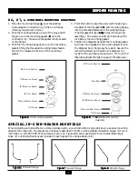
WIRING DIAGRAMS
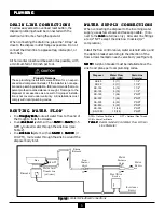
WIRING DIAGRAMS
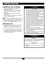
WIRING DIAGRAMS
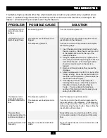
WIRING DIAGRAMS
WIRING DIAGRAMS
ELECTRICAL CONNECTIONS
ELECTRICAL CONNECTIONS
ELECTRICAL CONNECTIONS
ELECTRICAL CONNECTIONS
ELECTRICAL CONNECTIONS
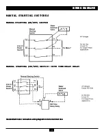
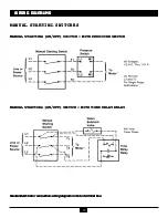
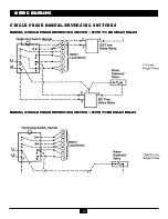
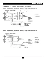
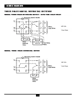
These electrical diagrams are recommended for the most commonly used accessory combinations. Wiring dia-
grams for other accessory combinations may be requested by calling In-Sink-Erator at 1-800 558-5700.
NOTES:
NOTES:
NOTES:
NOTES:
NOTES: • All electrical connections must comply with local electrical codes.
• Pressure switches may be connected across the line at 5 horsepower or less. (Larger horsepower
motors require connection in the pilot circuit of a magnetic starter.)
• The magnetic and manual starters supplied by In-Sink-Erator do not require heaters to complete the
circuit (In-Sink-Erator disposers are equipped with overload protectors).
• A time delay relay may only be used with a water solenoid valve.
380/460 Volts
50/60 HZ
Three Phase
208/230 Volts
50/60 HZ
Three Phase
208/230 Volts
50/60 HZ
Single Phase
120 Volts
50/60 HZ
Single Phase
Содержание 13954
Страница 1: ......


