


NVC210
User’s Guide
Rev.1.2 (Aug. 2009)
10
10
10
10 of 56
of 56
of 56
of 56
Interface Description
Interface Description
Interface Description
Interface Description
No.
Interface
Description
1
Auto-Iris Connector
For use with DC based Auto-Iris Lens
2
CS Lens Mount Ring
Lens Mount Interface For CS Type Lens. To Use C Type Lens, a
CS to C Type Lens Adapter is Needed.
3
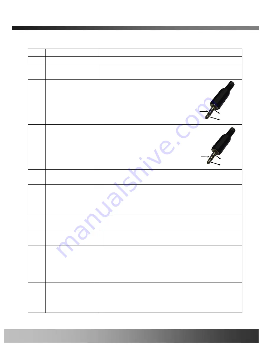
Audio Line Out
3.5 mm 3 conductor mini-jack external
speaker or PA system interface.
Standard 3.5mm stereo jack and
amplified speakers are needed. The
electrical connection notes are noted
in the jack image to the right.
4
Audio/MIC In
3.5 mm 3 conductor mini-jack external
Audio Line In or Microphone Input
interface. A standard 3.5mm stereo
jack is needed. The electrical
connection notes are noted in the jack
image to the right.
5
RJ45 Jack
10/100 Base-Tx Network Interface with IEEE 802.3af Power Over
Ethernet Capability
6
Hardware Reset Pin
Restore to factory default configuration. There is a switch provided
for returning the network camera to factory default state. Press the
switch through a tiny hole at the left of the 100BaseT connector
using tools with sharp tip for a few seconds while power is applied.
7
Power Connector
Local 12VDC power input. Do not use local power connector when
PoE is used.
8
Alarm Out
Controls 1 set of dry contact relay. The relay can be set to
normally open or normally closed contact.
9
Alarm In
Attached 1 set of dry contact sensor into the alarm/sensor input
connector to trigger recording or relay output. Most common
sensors are infrared sensor, heat sensor, magnetic sensor, etc.
Please refer to Section 6.1 for more detailed description on the
Alarm In/Out connections.
10
RS-485 Connector
Output PTZ control to PTZ modules. Inscape Data cameras support
over 30 PTZ protocol drivers. Drivers maybe found on the product
CD-ROM and uploadable to the IP camera via the web management
interface.
Audio out
Ground
Not used
Audio out
Ground
Not used
Audio In
Ground
Not used
Audio In
Ground
Not used


