


4.2.20 357-05818-01 Rev A © Inovonics, 2020 - www.inovonics.com
2
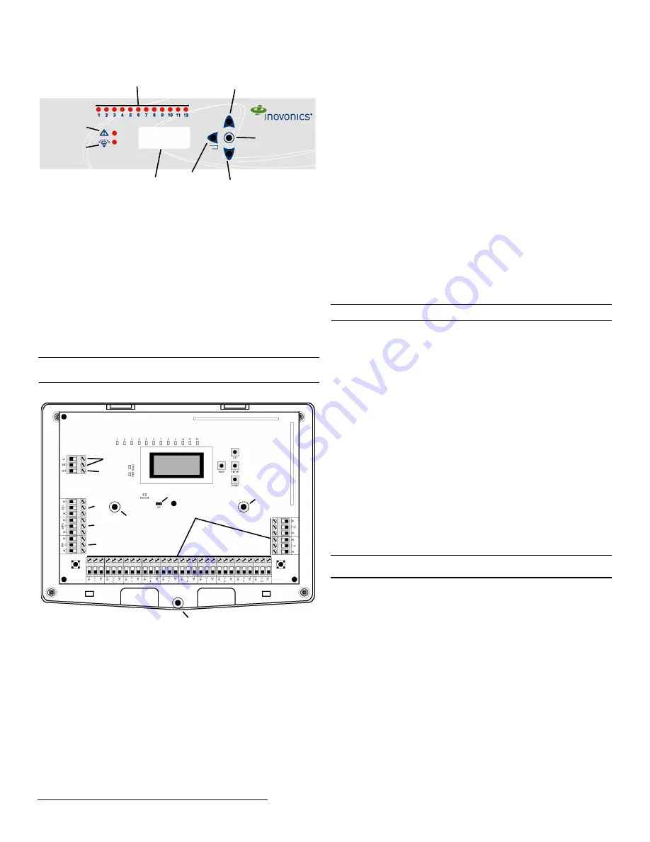
1.4 EE4232MR Front Panel
Figure 2
Receiver front panel
Up Button Scrolls the display up.
Down button: Scrolls the display down.
Back button: Returns display to the previous menu.
Enter button: Selects the currently displayed menu item.
LCD Display: Shows status, event log, and programming information.
Output LEDs: The output LEDs light to indicate an alarm or fault condition
at the appropriate output.
Fault LED: The fault LED lights to indicate a transmitter fault condition;
either low battery, inactive, line power loss, or tamper.
Power LED: The power LED lights when the EE4232MR is receiving
power.
Note:
The EE4232MR LCD will only display information when an
authorized password has been entered.
1.5 EE4232MR Internal Components
Figure 3
EE4232MR internal components
1.6 What’s in the Carton
• Two drywall mounting anchors.
• Two wall mount screws.
• One frequency band selection jumper.
2 Installation and Startup
2.1 Installation Notes
• These products are designed to be maintained by professional
security technicians.
• Products are tested for indoor use.
• All products should be manually tested weekly.
2.2 Power Cabling
Before beginning startup, you will need to connect power to the receiver. To
connect power to the receiver:
1.
Connect power cabling to the Vs and GND connections.
• The power source must be 11-14 VDC. The power supply must be
unswitched, uninterrupted, and regulated.
2.3 EchoStream Select Compatibility
To meet ETSI requirements, Inovonics has developed a new line of EE
868MHz-only products. These new 868MHz-only products are compatible
with older systems that include EchoStream Select products. If you are
using any ES products in your current system, you will need to enable
EchoStream select compatibility on this 868MHz-only product; if you are
not using any EchoStream select products, skip to section 2.4, “Input/
Output Cabling”.
To enable EchoStream Select compatibility:
2.
Place a selection jumper on the ES selection pins.
Note:
Selection jumpers are included in the EE4232MR hardware packet.
3.
Reset the receiver or cycle power.
2.4 Input/Output Cabling
Connect the inputs and outputs per your specific application:
4.
Connect cabling to the clear to set output.
• The optional clear to set output is a relay output that provides a clear
to set signal to the control panel that can be used to ensure all security
devices in the system are active before allowing the system to be set.
If used, the system cannot be set if the receiver has not heard from
any registered wireless devices within the last 20 minutes.
5.
Connect cabling to the tamper output.
• The optional tamper output is a relay output that reports receiver case
tamper to an external device.
6.
Connect cabling to the jam output.
• The optional jam output is a relay output that is active when noise
thresholds on all transmission channels remain above a
predetermined value for 30 seconds in any 60 second window.
7.
Connect a momentary switch to the reset input and ground.
• The optional reset input circuit permits installation of a remote
momentary normally open (N/O) switch to clear faults, unlatch
outputs, and reset the receiver to a normal state.
8.
Connect cabling to the output terminals.
9.
Mount the Receiver
Caution:
Mount the receiver in a location removed from metal. Metal
objects (duct work, wire mesh screens, boxes) will reduce RF range.
10.
Use the provided anchors and screws to mount the receiver in a
location accessible for future maintenance, making sure the housing is
flush with the wall and the back tamper switch is actuated.
11.
After all transmitters have been registered, perform a walk test,
activating each transmitter assigned to the receiver and ensuring a
good signal.
2.5 Select Display Language
On initial startup you will need to select the display language. Once
selected, the language will be maintained unless changed using the
C
HANGE
L
ANGUAGE
option in the I
NSTALL
& S
ERVICE
menu. To change the
display language, see “Select Language” on page 5.
3 Factory Configuration Defaults
The EE4232MR arrives with the outputs pre-programmed. If the default
programming is sufficient for your site, you can advance directly to section
“Register Transmitter” on page 6.
A
Up button
B
Down
button
C
Back
button
D
Enter button
E
LCD
display
F
Output
LEDs
G
Fault LED
H
Power LED
A
Housing release
screw
B
Power connections
C
Reset input
D
Output terminals
E
Clear to set output
F
Tamper output
G
Jam output
H
ES selection pins
I
Mounting holes
D
G
A
B
C
E
H
F
B
A
E
F
G
D
H
I
I
C


