


9
©1996-1997 - INLINE, INC. IN2000 / IN2001 OPERATION MANUAL - REV. 2.1 12/11/99
Horizontal Blanking Control (TTL Only)
The Horizontal Blanking Control functions only with TTL digital input signals. This control (location
shown on Page 8) will not need to be adjusted on a regular basis. The following image symptoms may
indicate that the control is misadjusted: missing background colors, horizontal dark bars across the
screen, or missing foreground colors. Before adjusting the Horizontal Blanking Control, first check to
make sure that the external Horizontal Position Control (Page 6) is not causing any image problems. The
following procedure is recommended for adjusting the Horizontal Blanking Control:
1.
IN2000 - Disconnect power and open the case.
IN2001 - Leave power on during adjustment. Turn unit over to access the dip switches
and Horizontal Blanking Control pot located on the bottom of the unit.
2.
Activate the Blanking Control Pot by turning Dip Switch #10 to ON.
3.
Adjust the control pot until the image quality improves and all the left hand edge of the
screen is displayed properly without being cut off.
DIP SWITCH SETTINGS
Most installations will not require any changes to the dip switch settings, and the IN2000 / IN2001 will
generally be operated with the factory default settings. The Factory Default setting and specialized dip
switch settings are indicated below.
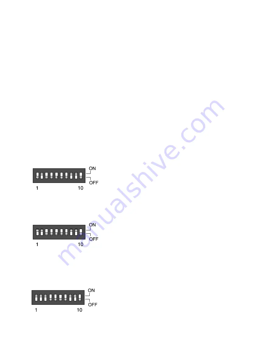
Factory Default Settings
Dip Switches ON:
2, 8 & 9
Signal Format:
Red / Green / Blue / Composite Sync
Horizontal Position Control: Active
Blanking Control:
Disabled
Sync on Green Output
Turn Dip Switch #1 to ON.
Dip Switches ON:
1, 2, 8 & 9
Signal Format:
Red / Green with Composite Sync /
Blue
Monochrome Output
Turn Dip Switches #1 and #3 to ON. This combines the red, green, and blue video into composite
monochrome. The monochrome signal is output on the GREEN connector.
Dip Switches ON:
1, 2, 3, 8 & 9
Signal Format:
Composite Monochrome


