


Z-Wave Temperature & Humidity Sensor
ZSENS930AW00MA Installer Guide
IMPORTANT
This sensor should be installed by a qualified HVAC technician.
After installation, allow 10 minutes for the temperature readings to stabilize.
NOTE : This document is intended for use with software version
5.3
when using this sensor with a Trane/American Standard connected thermostat. *
INSTALLATION
– adding a ZSENS930 to a new or existing Z-Wave network
STEP 1
– Find the right location
Suggested criteria for finding the right sensor location when used to control a home or as a
thermostat sensor:
1. Do not place near a supply register.
2. Do not place near windows or on an exterior wall.
3. Do not place behind doors or where air flow can be blocked by furniture.
4. Do not place where it may be subject to unnecessary or extreme temperature changes;
unintended influences may cause adverse environment sensing.
5. The optimum zone for correct placement of the sensor is at least 5 feet above the floor
and at least 2 feet below the ceiling.
STEP 2
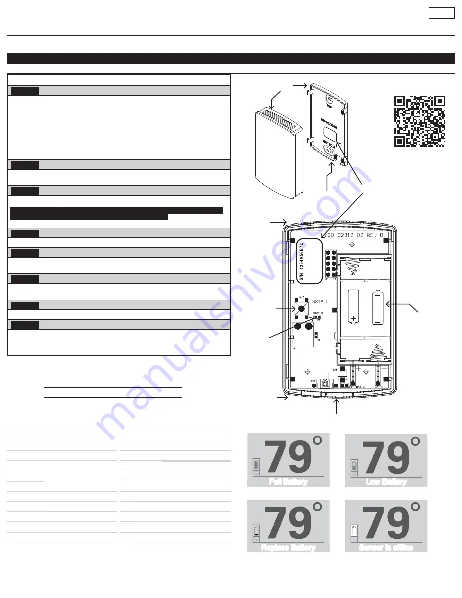
– Remove the Back Plate
Insert a small screwdriver beneath the tab at the bottom of the Back Plate and lift to unsnap
it from the front. WRITE DOWN the Serial Number from the Back Plate of the sensor.
STEP 3
– Insert the supplied batteries
Two 1.5 Volt AAA batteries are supplied in the box.
Please see Table 1. on Page-2 to continue with adding a wireless sensor
to the Z-Wave enabled 824, 850 and 1050 thermostats.
STEP 4
– Put the Z-Wave bridge in Add mode
Press the
+
or Add button on the bridge.
STEP 5
– Add the sensor
Stand where the sensor is to be installed and press and release the button labeled
“INSTALL” on the interior of the sensor
STEP 6
– Connection Status.
The status LED next to the button on the interior of the sensor will blink rapidly for 3
seconds when it has been added to your Z-Wave network.
STEP 7
– Mount the back plate at the right location
Anchors and screws are provided to mount the Back Plate.
STEP 8
– Mount the Sensor
FINAL INSTALLATION STEP
Once successfully added, snap the sensor onto the mounted Back Plate.
It will take 10 minutes after installation for the temperature and humidity values to stabilize
due to handling.
Top
Battery
Compartment
Bottom
Tab
Slot
INSTALL
Button
Status
LED
Front
Plate
Back
Plate
Tab
Top
Serial Number
Location
Scan the QR code to view help videos
SERIAL#
LOCATION
Or zone name if applicable
Home owner should retain a copy of this document for their records.
ZONE NOTES:
LOCATION:
LOCATION / :
SERIAL#
SERIAL#
LOCATION:
LOCATION:
SERIAL#
SERIAL#
LOCATION:
LOCATION:
SERIAL#
SERIAL#
LOCATION:
LOCATION:
SERIAL#
SERIAL#
NOTE : Please see this link for video tutorials:
http://www.fieldtechhelp.com/comcon014.html
A QR Code at the top of this document is also available for your convenience.
The latest version of this document can be found on ComfortSite or ASDealernet.
* Instructions to add wireless sensors for previous software versions 5.1 to 5.2.5
may be found on ComfortSite or ASDealernet.
Sensor with lowest battery level is shown on home screen.
Full Battery
Replace Battery
Low Battery
Sensor is offline
Page - 1


