


22
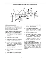
Adjustment Instructions
The operating pressure of this unit was set at
the factory to the maximum rating (at full speed)
See General Data. However, this pressure may
be reset down to 160 psi (1050 kPa)
Normally, regulation requires no adjusting; but if
proper adjustment is lost, proceed as follows:
1. Loosen bolt A. Adjust BFV until scribe mark
on end of BV shaft is 60
°
above horizontal.
Re-tighten A.
2. Loosen nut (E) to relax spring (G).
3. Loosen nut (H). Turn rod (L) in Air Cylinder
(AC) until there is approximately ¾ inch (20
mm) between nut (H) and flats on rod (L).
4. Turn rod (L) one round into rod end bearing.
Tighten nut (H). Rotate butterfly shaft/lever
(C), open and close, several times to assure
that linkage is not binding.
5. Take slack out of spring (G) by moving nuts
(E) and (F). Tighten nuts.
6. Start unit and allow to warm up for 3 to 5
minutes.
7. Activate “Service Air” switch if so equipped.
8. With service air valve closed, adjust
pressure regulator (PR) to rated pressure (*)
plus 10 psi (70kPa) as follows:
9. Loosen locknut (M) counterclockwise. Turn
adjustment cap (N) clockwise to increase
pressure, counterclockwise to decrease
pressure.
10. Bring driver engine to rated speed.
11. Open service air valve until lever C contacts
stop B. Adjust regulator to give rated
operating pressure (*). Tighten locknut (M).
12. To regulate to any pressure between 150
psi (1050kPa) and maximum rating (*),
make adjustments at the pressure regulator.
13. Note: For Dual Regulation –
Unit may be equipped with dual regulation. This
includes a second pressure regulator (PR2) set
at a lower pressure than the PR1.
Setting of
the PR2 must be between 150 and 250 psig.
Repeat steps 9-12 to set PR2 after selecting low
pressure range on customer panel. Any
override needle valve must be closed during this
procedure.
Pressure Regulation Adjusting Instructions
A
Содержание XHP1070CMH
Страница 2: ......
Страница 3: ......
Страница 4: ......
Страница 5: ......
Страница 6: ......
Страница 7: ......
Страница 8: ......
Страница 9: ......
Страница 10: ......
Страница 11: ......
Страница 12: ......
Страница 13: ......
Страница 14: ......
Страница 15: ......
Страница 16: ......
Страница 17: ......
Страница 18: ......
Страница 19: ......
Страница 20: ......
Страница 21: ......
Страница 23: ......
Страница 24: ......
Страница 26: ......
Страница 27: ......
Страница 28: ......
Страница 29: ......
Страница 30: ......
Страница 31: ......
Страница 32: ......
Страница 33: ......
Страница 34: ......
Страница 36: ......
Страница 37: ......
Страница 38: ......
Страница 39: ......
Страница 40: ......
Страница 41: ......
Страница 42: ......
Страница 43: ......
Страница 44: ......
Страница 45: ......
Страница 46: ......
Страница 47: ......
Страница 48: ......
Страница 49: ......
Страница 50: ......
Страница 51: ......
Страница 52: ......
Страница 53: ......
Страница 54: ......
Страница 55: ......
Страница 57: ......
Страница 58: ......
Страница 59: ......
Страница 60: ......
Страница 61: ......
Страница 62: ......
Страница 63: ......
Страница 64: ......
Страница 65: ......
Страница 66: ......
Страница 67: ......
Страница 68: ......
Страница 69: ......
Страница 70: ......
Страница 71: ......
Страница 72: ......


