Ingersoll-Rand TEM6A0B24H21SB Скачать руководство пользователя страница 8

8

18-GF74D1-1K-EN

contactor will close and start the compressor and
condenser fan motor.

C

Co

oo

olliin

ng

g ((h

he

ea

att p

pu

um

mp

p))

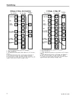
When the thermostat calls for cooling, the circuit
from R to G is completed. The blower motor is
energized directly by the ECM fan control, which
receives the 24VAC signal from the thermostat.

The circuit from R to Y is also complete energizing
the compressor contactor of the outdoor unit. The
contactor will close and start the compressor and
condenser fan motor.

Circuit R to O energizes the reversing valve to the
cooling position.

H

He

ea

attiin

ng

g ((h

he

ea

att p

pu

um

mp

p))

When the thermostat calls for heating, the circuit
from R to G is completed and the blower motor is
energized directly by the ECM fan control, which
receives the 24VAC signal from the thermostat.

The circuit from R to Y is also complete energizing
the compressor contactor of the outdoor unit. The
contactor will close and start the compressor and
condenser fan motor.

In the heating mode, the reversing valve of the
outdoor unit is not energized.

If the indoor temperature continues to fall, the R to
W circuit is completed energizing the electric heat
contactor(s).

H

He

ea

attiin

ng

g ((e

elle

eccttrriicc h

he

ea

att o

on

nlly

y))

N

No

otte

e:: The thermostat must be setup to bring the

blower on when the electric heat is energized.

When the thermostat calls for heating, the circuit
from R to G is completed and the blower motor is
energized directly by the ECM fan control, which
receives the 24VAC signal from the thermostat. The
circuit from R to W is completed energizing the
heating contactor(s).

D

De

effrro

osstt

Supplemental heat during defrost can be provided
by connecting the X2 (black) wire from the outdoor
unit to W1 or W2 at the indoor unit. This will
prevent cold air from being discharged from the
indoor unit during defrost.

13. O

Op

pe

erra

attiio

on

na

all a

an

nd

d C

Ch

he

ecckko

ou

utt P

Prro

occe

ed

du

urre

ess

To obtain proper performance, all units must be
operated and charge adjustments made in
accordance with procedures found in the Service
Facts document of the outdoor unit. After
installation has been completed, it is recommended
that the entire system be checked against the
checkout list located at the back of this document.
See

“Checkout Procedures,” p. 37

14. M

Ma

aiin

ntte

en

na

an

ncce

e

The system air filter(s) should be inspected, cleaned
or replaced at least monthly. Make certain that the
access panels are replaced and secured properly
before placing the unit back in operation. This
product is designed for dependable service;
however, periodic maintenance should be
scheduled and conducted by trained professional
service personnel. This service should be
conducted at least annually, and should include
testing and inspection of electrical and refrigerant
components. The heat transfer surface should be
cleaned. The blower motor is permanently
lubricated for normal operating conditions.

F

Fe

ea

attu

urre

ess

Содержание TEM6A0B24H21SB

Страница 1: ...rature and on the tags stickers and labels that are attached to the equipment March 2018 1 18 8 G GF F7 74 4D D1 1 1 1K K E EN N Convertible Air Handlers 2 5 Ton TEM6A0B24H21SB TEM6A0B30H21SB TEM6A0C3...

Страница 2: ...r rv vi ic ci in ng g a an nd d t tr ro ou ub bl le es sh ho oo ot ti in ng g o of f t th hi is s p pr ro od du uc ct t W WA AR RN NI IN NG G P PR RE ES SS SU UR RI IZ ZE ED D R RE EF FR RI IG GE ER R...

Страница 3: ...AR RE EA A G GE EN NT TL LY Y W WI IT TH H S SO OA AP P A AN ND D W WA AR RM M W WA AT TE ER R A AF FT TE ER R H HA AN ND DL LI IN NG G T Th hi is s w wa ar rn ni in ng g c co om mp pl li ie es s w w...

Страница 4: ...ta 11 Performance and Electrical Data 12 Minimum Airflow CFM 21 Outline Drawing 23 Heater Pressure Drop Table 24 Subcooling Adjustment 24 Subcooling Adjustment for TEM6A0C48H41 TEM6A0C60H51 24 Coil Co...

Страница 5: ...onal 1 4 rise over the width or depth of the unit is allowed to create additional sloping towards the drain Unit must be positioned between level and rise sloping toward the drain connections When the...

Страница 6: ...for air conditioning or heat pump operation Some outdoor models may require a start assist kit See outdoor unit for more information 7 B Bl lo ow we er r This unit is supplied with a variable speed m...

Страница 7: ...y wires shall be sized to the National Electric Code or local code requirements whichever is more stringent The unit is shipped wired for 230 240 Volt AC 60 HZ 1 Phase Operation If the unit is to be o...

Страница 8: ...the circuit from R to G is completed and the blower motor is energized directly by the ECM fan control which receives the 24VAC signal from the thermostat The circuit from R to W is completed energizi...

Страница 9: ...for multiple stages of electric heat jumper W1 and W2 together if comfort control has only one stage of heat Single Stage HP Thermostat Air Handler Outdoor Unit R G B W1 W2 R B O Y X2 R G B O Y W1 Bl...

Страница 10: ...lectric heat jumper W1 and W2 together if comfort control has only one stage of heat 2 Stage 2 Step HP Thermostat Air Handler Outdoor Unit R G B W1 W2 R B O Y1 X2 R G B O Y1 W1 Blue 24 VAC HOT FAN 24...

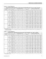
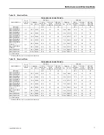
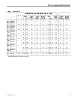
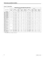
Страница 11: ...18 GF74D1 1K EN 11 Electrical Data...

Страница 12: ...211 830 242 727 268 HIGH 383 CFM ton ON OFF ON OFF CFM Watts 963 172 973 223 995 263 967 291 844 308 a Factory Default Setting Table 5 Air Flow Performance TEM6A0B24H21SB HEATING AIRFLOW PERFORMANCE N...

Страница 13: ...138 1004 194 1022 258 1000 326 947 397 a Factory Default Setting Table 7 Air Flow Performance TEM6A0B30H21SB HEATING AIRFLOW PERFORMANCE NO FILTER NO HEATER OUTDOOR UNIT SIZE TONS SPEED SETTING AIRFLO...

Страница 14: ...93 1528 436 1473 466 1406 483 1326 488 a Factory Default Setting Table 9 Air Flow Performance TEM6A0C36H31SB TEM6A0C42H41SB HEATING AIRFLOW PERFORMANCE NO FILTER NO HEATER OUTDOOR UNIT SIZE TONS SPEED...

Страница 15: ...ed 1800 cfm in horizontal right horizontal left and downflow applications due to condensate blowoff The 5 ton high tap shall not be used in these applications Table 11 Air Flow Performance TEM6A0C48H4...

Страница 16: ...476 1892 556 1900 635 1902 714 1760 650 a Factory Default Setting Table 13 Air Flow Performance TEM6A0D48H41SB TEM6A0D60H51SB HEATING AIRFLOW PERFORMANCE NO FILTER NO HEATER OUTDOOR UNIT SIZE TONS SP...

Страница 17: ...45 Motor Amps a MCA and MOP for circuit 1 contains the motor amps Table 15 Electrical Data TEM6A0B30H21SB HEATER DATA Heater Model No No of Circuits Phases 240 Volt 208 Volt Capacity Heater Amps per C...

Страница 18: ...YHTR1508BRK BAYHTR1508LUG 1 1 7 68 26200 32 0 45 45 5 76 19700 27 7 40 40 BAYHTR1510BRK BAYHTR1510LUG 1 1 9 60 32800 40 0 55 60 7 20 24600 34 6 49 50 BAYHTR1517BRK Circuit 1 a 2 1 9 60 32800 40 0 55 6...

Страница 19: ...34 6 52 60 BAYHTR1517BRK Circuit 1 a 2 1 9 60 32800 40 0 59 60 7 20 24600 34 6 52 60 BAYHTR1517BRK Circuit 2 4 80 16400 20 0 25 25 3 60 12300 17 3 22 25 BAYHTR1523BRK Circuit 1 a 2 1 9 60 32800 40 0 5...

Страница 20: ...34 6 52 60 BAYHTR1517BRK Circuit 1 a 2 1 9 60 32800 40 0 59 60 7 20 24600 34 6 52 60 BAYHTR1517BRK Circuit 2 4 80 16400 20 0 25 25 3 60 12300 17 3 22 25 BAYHTR1523BRK Circuit 1 a 2 1 9 60 32800 40 0 5...

Страница 21: ...1000 820 BAYHTR3510LUG 875 820 BAYHTR3517LUG 1000 950 BAYHTR1523BRK 1300 1140 TEM6A0C48H41SB TEM6A0C60H51SB Heater Minimum Heater Airflow CFM With Heat Pump Without Heat Pump BAYHTR1504BRK BAYHTR1504L...

Страница 22: ...7 Switch 8 Low ON ON 696 Med Lo OFF ON 825 Med Hi ON OFF 1150 High OFF OFF 1298 TEM6A0C48H41SB TEM6A0C60H51SB Airflow Performance with Auxiliary Heat Airflow Settings Dip Switch Settings Nominal Airfl...

Страница 23: ...PRODUCT DIMENSIONS Air Handler Model A B C D E F H Flow Control Gas Line Braze TEM6A0B24 30 46 77 18 50 16 50 16 75 4 68 7 33 20 09 TXV 3 4 TEM6A0C36 42 51 27 23 50 21 50 21 75 7 01 9 66 24 59 TXV 7...

Страница 24: ...1525 4 700 0 01 0 02 600 0 01 0 02 Subcooling Adjustment System Matched with Indoor Unit Model No Outdoor Model No Subcooling 16 SEER HP 2 ton TEM6A0C36H31 4TWR6024H1000A 4TWX6024H1000A 4A6H6024H1000A...

Страница 25: ...The TEM6A0C48 and TEM6A0C60 will have a coil retaining bracket and a shipping bracket All other coils will have two coil retaining brackets 3 Remove the two screws holding the center horizontal brack...

Страница 26: ...at hold the coil support brackets and retain for later use Seal the holes to prevent air leakage 7 Rotate and lift the two coil support brackets to remove from front slots in cabinet Figure 8 All mode...

Страница 27: ...et removed in Step 3 Use the screws retained from Step 3 to attach 12 Place coil support brackets into the lower set of slots and rotate into place Push downward to lock into place 13 Secure each brac...

Страница 28: ...l assembly back into the air handler cabinet as shown 16 Remove the appropriate knock out for the condensate piping Figure 12 TEM8A0C48 and TEM8A0C60 Only Figure 13 All other models 17 Replace all pan...

Страница 29: ...ipping bracket All other coils will have two coil retaining brackets 3 Remove the two screws holding the center horizontal bracket and rotate out of place Retain parts Figure 16 TEM8A0C48 and TEM8A0C6...

Страница 30: ...rtant The coil slabs are different and the mount hole locations will vary See the illustrations on the following pages that correspond to the unit tonnage to see the correct mounting position of the w...

Страница 31: ...e on tube sheet TEM6A0B24 and TEM6A0B30 Front view Replace 2 screws and water diverter bracket Figure 23 TEM6A0B24 and TEM6A0B30 Rear view Remove 2 screws and water diverter bracket Figure 24 Screw is...

Страница 32: ...Replace 3 screws and water diverter bracket TEM6A0C36 and TEM6A0C42 models Front view Figure 27 Remove 3 screws and water diverter bracket TEM6A0C36 and TEM6A0C42 models Rear view Figure 28 Screw is...

Страница 33: ...Replace 3 screws and water diverter bracket Figure 31 TEM6A0D48 and TEM6A0D60 models Rear view Remove 3 screws and water diverter bracket Figure 32 TEM6A0D48 and TEM6A0D60 models Rear view Replace 3...

Страница 34: ...s and the drain pan support bracket from the front of the drain pan and insert them in the drains at the rear of the drain pan Note For the TEM6A0C48 and TEM6A0C60 the drain pan support bracket should...

Страница 35: ...nit in Step 12 Figure 36 All other models 12 Slide the coil assembly back into the air handler cabinet Important Make sure that the coil corner locks in place under the tab in the side left bracket to...

Страница 36: ...in Step 3 15 Replace the two coil retaining brackets removed in a previous step Note The TEM6A0C48 and TEM6A0C60 will have only one coil retaining bracket 16 Replace all panels Figure 38 TEM6A0C48 an...

Страница 37: ...ng shipment Adjust tubing if necessary so tubes do not rub against each other or any component when unit runs Ductwork is sealed and insulated All drain lines are clear with joints properly sealed Pou...

Страница 38: ...38 18 GF74D1 1K EN N No ot te es s...

Страница 39: ...18 GF74D1 1K EN 39 N No ot te es s...

Страница 40: ...protect food and perishables and increase industrial productivity and efficiency We are a global business committed to a world of sustainable progress and enduring results ingersollrand com Ingersoll...

Отзывы: