25
Brake Adjustment Procedure (optional feature)
NOTICE
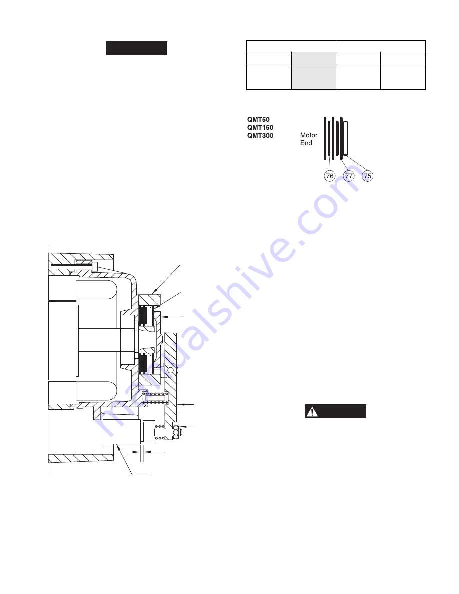
• By releasing the disc brake (careful apply pressure on the
brake lever (82) Dwg. MH1083), the trolley can be moved in
a manual mode.
• Replace brake discs if they are distorted or severely
discolored.
Follow the correct installation procedure for the brake discs.
Refer to Dwg. MHP0826.
1.
Turn locknut (97) until air gap ‘S’ is established. Refer to
Table 5.
2.
Push brake solenoid in and rotate cup disc (74) with
fingers. Disc should rotate with a little drag. Adjust locknut
until disc rotates with a little drag. If cup disc is too loose
the brake will chatter or hum during operation.
3.
Repeat steps 1 and 2 until air gap ‘S’ is correct and cup disc
just rotates.
Test
1.
With cover off, operate trolley, in low speed mode, along
the beam.
2.
Listen to brake during travel.
3.
When control button is released, brake should stop trolley
travel.
‘S’ (air gap)
Brake
Cage (78)
Brake Disc
Assembly
Brake
Lever (82)
Brake
Solenoid
Adjuster
Locknut (97)
Cup Disc (74)
(Dwg. MHP1083)
Table 5 Brake Disc Chart
Air Gap ‘S’
Number of Discs
in
mm
internal
external
0.060
to
0.079
1.5
to
2
2
3
Brake Assembly
(Dwg. MHP0826)
Disassembly
Refer to Dwg. MHP1005.
The following instructions provide the necessary information to
disassemble, inspect, and repair the trolley assembly. Parts
drawings are provided in the Parts Section to assist in locating
components.
If a trolley is being completely disassembled for any reason,
follow the order of topics as they are presented. When working
on a motorized trolley it is recommended that the unit be
removed from the overhead beam and placed on a clean work
bench in a well lighted area. In the process of disassembling the
trolley, observe the information provided in the General
Maintenance Instructions, also:
1.
Use a soft metal punch such as brass, when removing metal
shafts from housings.
2.
The gear lubricant is very messy and should be cleaned off
all parts and disposed of in accordance with local
procedures.
3.
When removing bearings from housings, drive out the
bearing with a sleeve slightly smaller than the outside
diameter of the bearing. The end of the sleeve or pipe that
is used to contact the bearing must be square. Protect
bearings from dirt by keeping them wrapped in clean
cloths.
WARNING
• Quantum hoist assemblies can weight up to 172 lbs (78 kgs).
Use adequate support during removal.
• Disconnect power from trolley and hoist assembly.
• Mark area to inform personnel trolley is being serviced.
Hoist Removal
1.
Remove screws (2) from relay box cover (1) and remove
cover (1) and gasket (3).
2.
Disconnect the incoming power leads from the terminal
strip going to the hoist. Refer to Dwg. MHP0970.
3.
Disconnect the hoist control leads from the terminal strip to
the hoist.
4.
Loosen the cable connectors (19) and pull both cables free
from relay box (18).
5.
Remove hoist.
Содержание QMT150
Страница 30: ...30 TROLLEY ASSEMBLY PARTS DRAWING Dwg MHP1005 ...


