background image

Form MHD56298

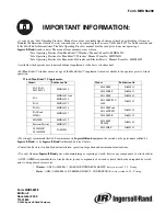
• A copy of our “Safe Operating Practices” Manuals are always available free of charge either by downloading it from our 
Technical Publications website @ www.airwinch.com or by contacting the Factory at (800) 866-5457 for North America and 
(206) 624-0466 for International. The Safe Operating Practices manual must be read prior to anyone operating a 

Ingersoll-Rand

 winch or hoist. The manual form numbers are as follows:

“Safe Operating Practices Non-Man Rider™ Winches” Manual, Form No. MHD56250 
“Safe Operating Practices for Man Rider™ Winches” Manual, Form No. MHD56251 
“Safe Operating Practices for Pneumatic, Hydraulic and Electric Hoists” Manual, Form No. MHD56295

• Available winch options may require additional supplements to the basic winch manual.

• For Man Rider™ winches ensure a copy of the Man Rider™ supplement is made available to the operator prior to winch 
operation.

• We strongly recommend that ALL maintenance on 

Ingersoll-Rand

 equipment be carried out by personnel certified by 

Ingersoll-Rand

, or by 

Ingersoll-Rand

 Authorized Service Centers.

• Contact the Factory if in doubt about installation, operation, inspection and maintenance instructions.

• Use only Genuine 

Ingersoll-Rand

 parts when maintaining or repairing a winch, hoist or any component of a winch or hoist.

• ANSI / ASME recommends that a winch or hoist (or any components of a winch or hoist) that has been repaired be tested 
prior to being placed into service:

Winch Man Rider

 Supplements:

Model:

Publication No.

Model:

Publication No.

FA2, FA2.5, 
FH2, FH2.5

MHD56046

LS500RLP

SAM0011

LS1000RLP

SAM0012

FA5 

MHD56042 and 
MHD56220

LS150RLP

SAM0082

LS150RLP/500/
1000

SAM0115

FA10

MHD56252

FA2.5A MHD56236

LS150RLP and 
LS150PLP-PH

SAM0120

FA2B and 
HU40A

MHD56207

LS500RLP-E

SAM0122

FH10MR

MHD56212

LS150RLP-
DP5M-F

SAM0184

Fulcrum Electric

MHD56277

LS500HLP/
LS1000HLP

SAM0004

LS150HLP

SAM0222

*

Winches  - 

ANSI / ASME B30.7 (BASE MOUNTED DRUM HOISTS) Refer to section 7.2.2 - Testing.

*

Hoists - 

ANSI / ASME B30.16 (OVERHEAD HOISTS - UNDERHUNG) Refer to section 16.2.2 - Testing.

Form MHD56298
Edition 2
November 2004
71441844

© 

2004 Ingersoll-Rand Company

IMPORTANT INFORMATION:

Содержание force 5 Man-Rider FA2.5MRA

Страница 1: ...ied out by personnel certified by Ingersoll Rand or by Ingersoll Rand Authorized Service Centers Contact the Factory if in doubt about installation operation inspection and maintenance instructions Us...

Страница 2: ...persons responsible for the operation installation and maintenance of these products The winch is only part of the Personnel Lifting System For information defining the Personnel Lifting System requir...

Страница 3: ...1 Winch ComponentOperation 12 Winch EmergencyDescentProcedure 12 Training 13 Winch Lubrication Recommended Lubricants 13 Motor 13 Wire Rope 14 ReductionGearAssembly 14 Disc Brake optional feature 14 S...

Страница 4: ...eddrum hoists as defined by ASME B30 7 and for the purposeof personnel handling asdefined by ANSI A10 22 1990 In furnishing customersMan Rider winches Ingersoll Rand doesnot warrant the suitability of...

Страница 5: ...ionfor applicableutility andManRider capacity ratings 6 7 8 9 10 11 12 13 14 15 16 17 18 19 20 21 Prior to use inspect andtestthepersonnellifting systemto therequirementsof ANSI A10 22 Section 13 Insp...

Страница 6: ...inches Wire Rope Diameter 8 269 feet 12 404 feet 16 539 feet 24 808 feet 30 1010feet FA2 5 Utility rating of 3 500Ibs 1 558kg is basedon requirementsof ASME B30 7 5 l designfactor with 7 16 inch 11 mm...

Страница 7: ...3 Adjustableupperandlower rotary limit switches 4 Pipedaway exhaustwith muffler and 10feet 3 metres of exhausthose Copy of OperationandMaintenanceManual andANSI A10 22 Standardsuppliedin 5 containerat...

Страница 8: ...drum for overwind operation ONLY Failure to correctly spool the wire rope will result in falling load which can cause severe injury death and property damage Refer to Dwg MHTPA0661 1 2 Ensurethe winc...

Страница 9: ...ayer is a minimum of 2 inches 51 mm below drum flange edge Refer to Dwg MHTPA0498 l To prevent wire rope line run ensure a weight greater than the total weight of the longest wire rope pay out to shea...

Страница 10: ...l the wire rope anchorinto position in the drum anchorpocket l Wire rope must be spooled at least 2 inches 51 mm below the outer diameter of the drum flange Refer to Dwg MHTPA0498 Rigging Make sureall...

Страница 11: ...ANSI A10 22 standards Ensure electrical grounding is conducted by licensed electricians in accordance with the latest edition of the National Electric Code ANSI NFPA 70 and any applicable local state...

Страница 12: ...in the WINCH OPERATION section 1 Supervisors operatorsandpersonnelbeing lifted should checkthat winch wire rope working platform lifelines safetybelts harnesses etc arepresentand functional prior to a...

Страница 13: ...in by stopping air flow to the winch motor when asetpoint hasbeenreached It is the owner sand operator sresponsibility to adjustwinch operating limits prior to using the winch to transportpersonnel To...

Страница 14: ...HECKS Checkflow andlevelof airline lubricator approximately 6to9drops perminuterequiredatmaximum motorspeed Monthly Checkwinchmotoroil level Lubricatecomponents suppliedby grease fittings Inspectandcl...

Страница 15: ...n Drum Reduction Gear Dwg MHTPA0140 Drum Brakes Lubricate pivot points pins andshaftswith recommended greaseto preventcorrosion of parts l Do not allow grease or oil to come into contact with drum ban...

Страница 16: ...Lifting System components are made with respect to their relationship to the winch For specific information on system components other than the winch reference the manufacturers literature and ANSI A...

Страница 17: ...rols brakes siderails anddrum for indications of damage Do not operatethe winch until all discrepanciesnotedhavebeenreviewed inspected further andcorrectedby personnelinstructed in the operation safet...

Страница 18: ...rein good condition andtight LABELS AND TAGS WEEKLY Check for presenceandlegibility of labels Replaceif damaged or missing 10 WIRE ROPELINE SPEEDMONITOR Verify Line SpeedMonitor displays line speedand...

Страница 19: ...o appropriate and codes of practice If in doubt about an existing condition contact the nearest Ingersoll Rand Distributor or the factory for technical assistance CONDITION CORRECTIVE COMPONENT ACTION...

Страница 20: ...kage is found Shift pilot valve throttle lever in oppositedirection If winch operates adjustlimit switch settings Removeshipping plugs in valve andmotor exhaust ports Checkbrakebandadjustmentandbrakeb...

Страница 21: ...no air escapes replacedumpvalve Ensuresupply air pressureatthebrakeinlet is atleast50 psig 3 4 bar No releasepressureat the brakeport Verify properoperationof winch controls Low air supply pressure L...

Страница 22: ...top of thebrake housing during reassembly Manual Drum Brake Adjustment 1 Releasewire rope tension on the drum 2 Raisehandle 104 to free brakebands 3 Removecotter pin 102 andpin 101 4 Rotatelink stud 1...

Страница 23: ...rope at desiredpay out position 4 Rotatetheright camadjustmentscrewclockwise until it fully activatesthe cutoff valve causingsystemair to vent 2 3 4 turns of the camadjustmentscreware required for eac...

Страница 24: ...the air lines by operatingthe winch control severaltimes after the air supply has beenturned off l Shut off bleed down and disconnect the air supply line before performing any disassembly procedures...

Страница 25: ...ction gearassembly l Do not disassemble planetary gears from their from thedrum 80 To disassemblereduction gear carriers unless required to replace damaged parts For information on the planetary assem...

Страница 26: ...for worn cracked or broken teeth 2 Inspect all bushingsfor wear scoring or galling 3 4 5 6 Inspect shaftsfor ridges causedby wear If ridges causedby wearareapparenton shafts replacethe shaft Inspect a...

Страница 27: ...iston 204 with its rings 202and207 to the connecting rod 206 with wrist pin 203 andretaining rings 205 Install anewcylinder headgasket 209 before installing thecylinder liner 208 Install thecylinder l...

Страница 28: ...kelever 105 to brakeband 128 Install cylinder 110 soit connectswith bracket 118 andbrakelever 105 Usepins 106 andcotter pins 102 to securein position Install dump valve 112 fittings andhose 115 to the...

Страница 29: ...l with lockwashers 46 Torque to 70 ft lbs 95 Nm Install fill drain plugs 48 in gearcarrier 47 Apply athin coatof Loctite 609to the outside of seal 43 andinstall in gearcarrier 47 Placedrum in anuprigh...

Страница 30: ...rum band brakemust stopandhold testload when the winch throttle lever is placed in the neutral position Manual drum bandbrakemust beable to stopandhold test load when the winch throttle lever is place...

Страница 31: ...Dwg MHTPA0669 30...

Страница 32: ...181 SideRail 8 in drum 23708 l 47 GearCarrier 1 15451 SideRail 12 in drum 23708 2 48 PipePlug 2 51467 83 SideRail 16 in drum 1 23708 3 SideRail 24 in drum 23708 4 50 RetainerRing 1 51479 SideRail 30 i...

Страница 33: ...Dwg MHTPA0690...

Страница 34: ...commendedspare Partsnot sold separately Referto the Motor AssemblyKit List Motor Assembly consistsof items200through 255 Motor Assembly Kit List ITEM DESCRIPTION NO OF PART 231 Crank Assembly Includes...

Страница 35: ...Dwg MHTPB0636 34...

Страница 36: ...reather Cylinder 1 52384 1 4575 l 111 Fitting 1 52006 113 114 Fitting Hose 2 52385 Fitting Elbow 1 52330 115 116 Hose ICapscrew 1 50923 3 50873 117 Lockwasher 6 50181 118 Bracket 1 11493 119 Capscrew...

Страница 37: ...Dwg MHTPB0633 36...

Страница 38: ...361 Fitting Tee HoseAssembly HoseAssembly 1 Contact factory Specify Length in Feet 50923 Retainer 1 19232 Spacer 3 14998 7 Bracket Limit Switch 1 11501 505 Lockwasher 4 52909 506 Nut 4 54142 507 Coupl...

Страница 39: ...m 11283 5 150 151 Drum GuardAssembly 30 inch long drum 11283 6 Capscrew 4 71072243 Clamp 4 10399 152 support 2 10400 Drum Guard 8 inch long drum 11259 l Drum Guard 12 inch long drum 11259 2 153 Drum G...

Страница 40: ...End Cap Inlet Side 1 11778 269 Capscrew 8 52234 270 Adjusting Screw 1 71083968 271 Nut 1 52265 272 Shoulder Screw I 1 I 817 002 273 Guide 1 52233 274 Spring 1 52240 275 Washer 1 52239 276 Spacer 52238...

Страница 41: ...Dwg MHTPB0632 40...

Страница 42: ...335 Adapter Manifold 1 50893 __ _ 336 Tube Assembly 1 337 Capscrew 4 50829 338 Fitting Nipple 4 51814 339 Fitting Tee 4 54678 341 Fitting Bushing 5 51034 342 343 Fitting Elbow 1 71034714 Valve 1 50277...

Страница 43: ...Dwg MHTPA0643 42...

Страница 44: ...Dwg MHTPA0760...

Страница 45: ...MBER NO OF PART TOTAL NUMBER 1 Capscrew 8 51471 21 BrakeHousing 1 11322 Fitting Reducer 1 51803 6 Motor Adapter 1 14227 24 PipePlug 1 50801 7 ShaftExtender 1 10594 25 Fitting Reducer 1 52182 8 BrakeRe...

Страница 46: ...ITEM DESCRIPTION NO OF LABEL QTY TOTAL PART NUMBER 604 89 608 609 610 IR Siderail Logo Drive Screw Exhaust Oil Air Supply 50915 71042196 71043616 71046395 618 619 620 Battery ChargerInput Ground Conn...

Страница 47: ...her than genuine Ingersoll Rand Material Handling parts may adversely affect the safe operation of this product Return Goods Policy Ingersoll Rand will not acceptany returned goodsfor warranty or serv...

Страница 48: ...o Productswhich I R hasdeterminedto havebeenmisusedor abused improperly maintainedby the user or where the malfunction or defectcanbeattributed to the useof non genuineI R parts This warranty gives yo...

Страница 49: ...A Phone 206 624 0466 Fax 206 624 6265 Canada National Sales Office Regional Warehouse Toronto Ontario 51WorcesterRoad Rexdale Ontario M9W 4K2 Phone 416 675 5611 Fax 416 675 6920 Order Desk Fax 416 674...

Отзывы: