


12
MHD56114 - Edition 4
Air Supply
The air supply must be clean, free from moisture and lubricated to
ensure optimum motor performance. Foreign particles, moisture
and lack of lubrication are the primary causes of premature motor
wear and breakdown. Using an air filter, lubricator and moisture
separator will improve overall winch performance and reduce
unscheduled down time.
The air consumption is 700 scfm (20 cu. m/min) at rated operating
pressure of 90 psig (6.3 bar/630 kPa) at the winch motor inlet. If
air supply varies from recommended, then winch performance
will change.
Air Lines
The inside diameter of the winch air supply lines must be at least
1-1/2 inch (38 mm). Before making final connections, all air
supply lines should be purged with clean, moisture free air or
nitrogen before connecting to winch inlet. Supply lines should be
as short and straight as installation conditions will permit. Long
transmission lines and excessive use of fittings, elbows, tees,
globe valves etc. cause a reduction in pressure due to restrictions
and surface friction in the lines.
Air Line Lubricator
Refer to Dwg. MHP0191 on page 12.
Always use an air line lubricator with these motors. The lubricator
must have an inlet and outlet at least as large as the inlet on the
motor directional control valve. Install the air line lubricator as
close to the air inlet on the motor as possible.
CAUTION
• Lubricator must be located no more than 10 ft. (3 m) from
the motor.
• Shut off air supply before filling air line lubricator.
The air line lubricator should be replenished daily and set to
provide 6 to 9 drops per minute of ISO VG 32 (SAE 10W) oil. A
fine mist will be exhausted from throttle control valve when air
line lubricator is functioning properly.
Air Line Filter
Refer to Dwg. MHP0191 on page 12.
Place the strainer/filter as close as practical to the motor air inlet
port, but upstream from, the lubricator, to prevent dirt from
entering the motor. The filter/strainer should provide 20 micron
filtration and include a moisture trap. Clean the filter/strainer
periodically to maintain its operating efficiency.
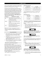
(Dwg. MHP0191)
Air Pressure Regulator
Refer to Dwg. MHP0191 on page 12.
If an air pressure regulator is used, install between the lubricator
and filter.
Moisture in Air Lines
Moisture that reaches the air motor through air supply lines is a
primary factor in determining the length of time between service
overhauls. Moisture traps can help to eliminate moisture. Other
methods, such as an air receiver which collects moisture before it
reaches the motor, or an aftercooler at the compressor that cools
the air to condense and collect moisture prior to distribution
through the supply lines are also helpful.
Ball Valve Shut Off
Refer to Dwg. MHP2459 on page 12.
Install in air supply line upstream of control valve. Ensure ball
valve is conveniently located and easily accessible. Advise
operators and support personnel of its location and use.
(Dwg. MHP2459)
Style
Description of Part
Part Number
Full Flow
Fitting, Nipple
51704
Ball Valve
71404628
Pilot Pendant Control
Fitting, Nipple
71311252
Ball Valve
71416911
Lubricator
Air Out
Regulator
Air In
Filter
Open
Closed
Ball Valve
Air
Flow
Fitting,
Nipple
Содержание FA2.5A Series
Страница 38: ...MHD56114 Edition 4 37 SERVICE NOTES...
Страница 70: ...MHD56114 Edition 4 69 SERVICE NOTES...
Страница 71: ...70 MHD56114 Edition 4 SERVICE NOTES...


