background image

Operating Manual 

To Capture a Still Image 

1)


Press the Yellow button. 

2)


The Capture symbol is displayed. 

3)


The Wait symbol is displayed adjacent to 

the memory location to signify the image is 

being saved. 


5.5


Browsing Saved Images (Image Capture only) 

 Information 

If no saved images are available, the thermal imager will automatically return to the Main Menu. 

If the Highlight Next File action is executed whilst the bottom-most file is highlighted, the 

thermal imager will automatically go to the next page and highlight the next available file. 

If the Highlight Previous File action is executed whilst the top-most file is highlighted, the 

thermal imager will automatically go to the previous page and highlight the next available file. 

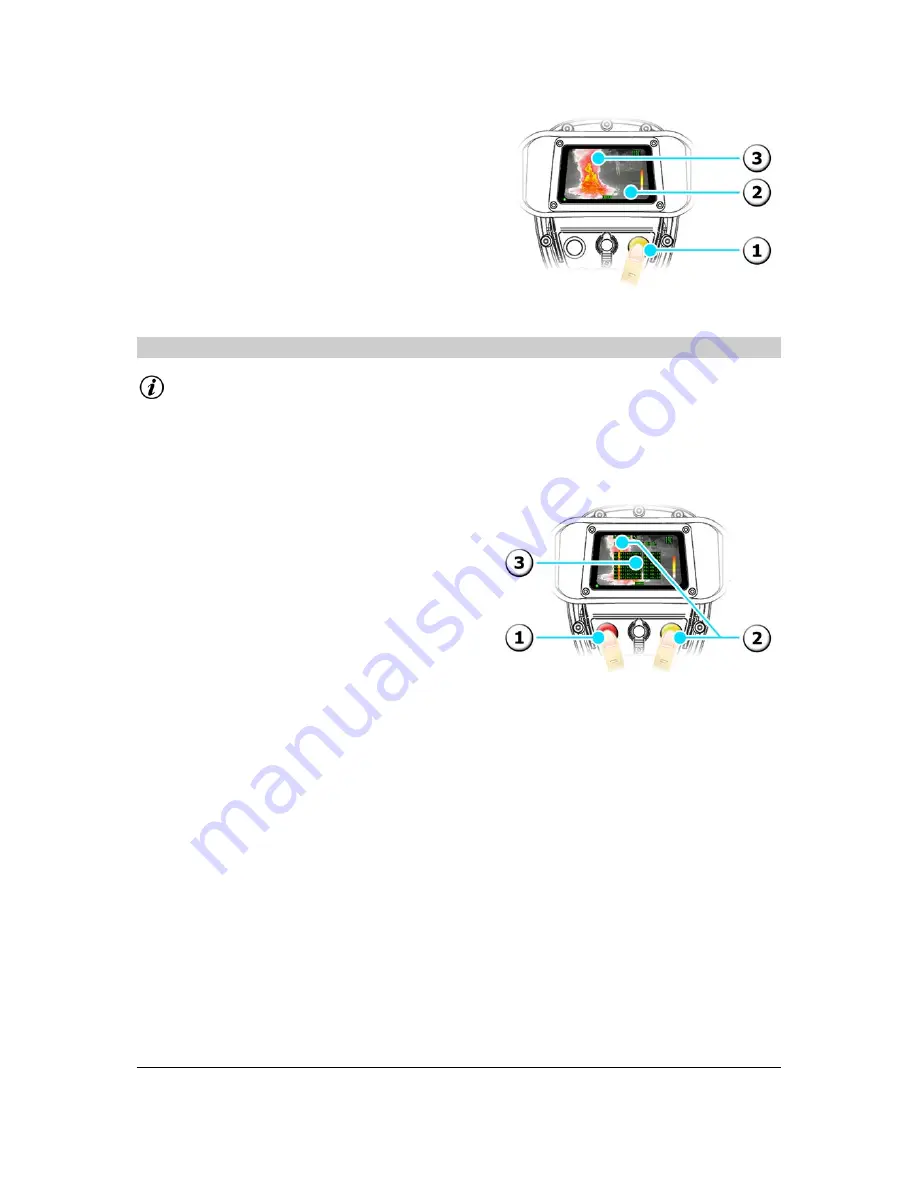
To Enter the Browse Menu 

1)


From Main Menu, highlight the Browse 

symbol. 

2)


Press the Yellow button to enter Browse 

Menu. 

3)


The file list is displayed in the middle of the 

screen and the first file in the list is 

automatically highlighted. 


© Copyright 2011, Infrared Systems Group Ltd. 


Page 22 of 34 

While ISG Infrasys has taken care to ensure the accuracy of the information contained herein, it accepts no responsibility for 

the consequences of any use thereof and reserves the right to change the specification of goods without notice. 

Содержание K1000

Страница 1: ...SD1000 K1000 Operating Manual ENGLISH K70 POM 001 A 3 Copyright 2014 Infrared Systems Group Ltd ...

Страница 2: ...surement Optional Feature 18 5 0 Advanced Operation 19 5 1 Main Menu 19 5 2 Zoom 20 5 3 Video Capture 20 5 4 Image Capture 21 5 5 Browsing Saved Images Image Capture only 22 5 6 Deleting Saved Files Image Capture only 23 5 7 Selecting a Colour Palette 24 5 8 Switching the Polarity 25 5 9 Internal Transmitter 25 5 10 Changing the Time Date Settings 26 6 0 Alternative Methods to View Live Thermal Im...

Страница 3: ...oduct to depict it s usage and operation This may differ from your purchased product however the functionality is exactly the same unless otherwise stated We strongly recommend that you read through the Regulatory Information in the next section of this Operating Manual prior to using your thermal imaging product for the first time 1 2 More Information Should you have any queries with regard to th...

Страница 4: ...h ISG INFRASYS and the customer Where an export licence applies a copy of the specific terms and conditions pertaining to this licence is enclosed with your product all users are encouraged to become familiar with them As an indicative but not exhaustive guide your ISG INFRASYS thermal imager s End User Licence Standard Conditions are reproduced in the next section 2 2 End User Licence Standard Co...

Страница 5: ...ons such as a controlled live burn situation Usage of the ISG INFRASYS thermal imager by unauthorised unfamiliar or untrained users in a hazardous atmosphere may result in injury or death 2 The ISG INFRASYS thermal imager is not life support equipment and should not be used as such 3 The ISG INFRASYS thermal imager provides a thermal image in normal vision impairing conditions and is designed to a...

Страница 6: ...ve oven it could explode and cause injury Never try to disassemble repair or otherwise tamper with a battery pack Never short circuit the battery pack by contacting the terminals with a metal object Never puncture the battery pack with a sharp object or strike with a hammer or other object 12 Users should be conscious of the battery life Only enter a hazardous environment when a full battery charg...

Страница 7: ...g optional accessories included in your accessory kit We recommend that you regularly check that each optional accessory is accounted for and is in good working order prior to use Optional Optional Optional Optional Optional Optional If you require more information on any optional accessory please visit our website at www isgfire co uk Kit 1 X1 Kit 2 X1 X2 X2 X1 X1 X1 X1 X1 X1 X1 Copyright 2011 In...

Страница 8: ...nd are ready for immediate use WARNING Do not expose the battery charger unit and or power adapter to rain or moisture Do not attempt to use a charging device to charge a non ISG INFRASYS approved battery To install your VMC or VMTC battery charger please refer to the installation guide enclosed Always check the charging device is in good working order before each use Copyright 2011 Infrared Syste...

Страница 9: ...wn to release the thermal imager Using a Vehicle Mount Twin Charger VMTC 1 Install device see installation guide 2 Insert thermal imager and or battery with external battery contacts facing in towards the charger into the appropriate charging station and secure using the strap s 3 Green LED steady battery is charged Undo strap s and remove 3 5 Preparing the AA Alkaline Battery Cassette Information...

Страница 10: ...s correct 3 Depress the button replace the inner cassette into the outer cassette and release to lock Copyright 2011 Infrared Systems Group Ltd Page 10 of 34 While ISG Infrasys has taken care to ensure the accuracy of the information contained herein it accepts no responsibility for the consequences of any use thereof and reserves the right to change the specification of goods without notice ...

Страница 11: ...aneously depress the release catches on either side of the battery 2 Slide the battery out of the compartment Copyright 2011 Infrared Systems Group Ltd Page 11 of 34 While ISG Infrasys has taken care to ensure the accuracy of the information contained herein it accepts no responsibility for the consequences of any use thereof and reserves the right to change the specification of goods without noti...

Страница 12: ...Refasten the strap and velcro hand pad Attaching a Lanyard 1 Push open the clip on the lanyard 2 Insert clip round the D ring and release Copyright 2011 Infrared Systems Group Ltd Page 12 of 34 While ISG Infrasys has taken care to ensure the accuracy of the information contained herein it accepts no responsibility for the consequences of any use thereof and reserves the right to change the specifi...

Страница 13: ...cks into place Removing a Grip Handle 3 Push the button on the grip downwards and slide the grip towards the front of the thermal imager until it is released Copyright 2011 Infrared Systems Group Ltd Page 13 of 34 While ISG Infrasys has taken care to ensure the accuracy of the information contained herein it accepts no responsibility for the consequences of any use thereof and reserves the right t...

Страница 14: ...n in the top right corner to signify the thermal imager is operating in Normal Imaging Mode Power Off 4 Press and hold the Red button 5 Release when the desired action symbol is displayed Power Off Abort Power Off 4 2 Understanding the On screen Display 1 Time Date if displayed 2 Crosshair 3 LED 4 DTM readout 5 Colour Reference Bar 6 Battery Bar Copyright 2011 Infrared Systems Group Ltd Page 14 of...

Страница 15: ...tter optional 18 Settings Menu 19 View File 20 Previous Page 21 Previous File 22 Next File 23 Next Page 24 Delete File 25 Delete All Files 26 Change the Day 27 Change the Month 28 Change the Year 29 Change the Hour 30 Change the Minute 31 Change the Second 32 Change Display Options 4 4 Focus Range This product uses an automatic focus feature that ensures the user can always receive the best detail...

Страница 16: ... in 1000 Mode and increases the user s effectiveness as well as their safety This image shows how ICETM improves visibility in practice Patent No GB2435977 4 6 Sensitivity Modes The ICETM system thermal imager incorporates two distinct sensitivity modes and selects the appropriate mode automatically by analysing the thermal characteristics of the scene Information When the thermal imager switches ...

Страница 17: ...on of the range of scene temperatures detected enabling rapid recognition of hot spots The Colour Reference Bar right is displayed on the right hand edge of the screen and provides a point of reference for the user to quickly identify the different temperature ranges in the scene 4 8 Direct Temperature Measurement The Direct Temperature Measurement DTM feature gives a temperature readout of a fixe...

Страница 18: ...M of the environment within a 50 cm radius of the product Additional factors can affect the accuracy of the ATM readout and therefore the feature should only be used as a guide and should never allow the user to deviate from their standard operating procedures The Ambient Temperature Measurement ATM feature gives the user a readout of the ambient air temperature of the immediate surrounding enviro...

Страница 19: ...ighlight the next action To Execute an Action in the Menu 2 Press the Yellow button to execute the highlighted action To Return to the Previous Menu 3 Press the Red button and the Yellow button together The Exit symbol is displayed and the thermal imager returns to the previous menu To Exit All Menus 4 Press and hold the Red button and the Yellow button together for 3 seconds approx The Exit symbo...

Страница 20: ... image is magnified by a factor of 4 and the X4 Zoom symbol is displayed Zoom Off 5 Press the Red button to exit 5 3 Video Capture Information The Video Capture feature is optional and therefore the following instructions may not apply Video Capture can be used when in Normal Imaging Mode or when using the Zoom feature Copyright 2011 Infrared Systems Group Ltd Page 20 of 34 While ISG Infrasys has ...

Страница 21: ...e LED flashes red and green alternately 4 Press the Yellow button to Stop 5 4 Image Capture Information The Image Capture feature is optional and therefore the following instructions may not apply Image Capture can be used when in Normal Imaging Mode or when using the Zoom feature Copyright 2011 Infrared Systems Group Ltd Page 21 of 34 While ISG Infrasys has taken care to ensure the accuracy of th...

Страница 22: ...ilable file If the Highlight Previous File action is executed whilst the top most file is highlighted the thermal imager will automatically go to the previous page and highlight the next available file To Enter the Browse Menu 1 From Main Menu highlight the Browse symbol 2 Press the Yellow button to enter Browse Menu 3 The file list is displayed in the middle of the screen and the first file in th...

Страница 23: ...age Capture only Information If all saved files have been deleted the thermal imager will automatically return to Main Menu If the delete action is aborted the thermal imager will automatically return to Browse Menu To Delete a Single File 1 Highlight the file and then from Browse Menu highlight the Delete Single File symbol 2 Press the Yellow button to go to the Confirm Delete Menu 3 Press the Ye...

Страница 24: ...l colour palette 3 Ironbow colour palette 4 Rainbow colour palette To Select a Colour Palette 5 From Main Menu highlight the Select Colour Palette symbol 6 Press the Yellow button to toggle between the available Colour Palettes 7 The palette will change to reflect the Colour Palette selected Copyright 2011 Infrared Systems Group Ltd Page 24 of 34 While ISG Infrasys has taken care to ensure the acc...

Страница 25: ... 2 Press the Yellow button to reverse the polarity 5 9 Internal Transmitter Information The Internal Transmitter is optional and therefore the following instructions may not apply To Switch On Off 1 From Main Menu highlight the Transmitter symbol 2 Press the Yellow button to toggle the transmitter On and Off Copyright 2011 Infrared Systems Group Ltd Page 25 of 34 While ISG Infrasys has taken care ...

Страница 26: ...tomatically highlighted To Change the Time Date Settings 4 From Settings Menu highlight the field you wish to change 5 Press the Yellow button The highlighted field will increment by a factor of 1 To Change the Display Settings 6 From Settings Menu highlight the Display Settings symbol 7 Press the Yellow button to toggle the Display Setting as appropriate Always display Only display when recording...

Страница 27: ... processor or equivalent Windows 2000 or XP operating system 256 Mb Internal RAM USB 1 1 2 0 CD ROM drive for software installation Information It may be necessary to adjust the settings on your PC e g Contrast Brightness etc to enhance the video quality and best reflect the live thermal image 1 Install the application using the installation instructions enclosed with the USB Video Kit 2 Connect t...

Страница 28: ... Remove the battery 2 Insert the Mini USB lead into the connector inside the battery compartment 3 Insert the USB lead into the port on your PC 4 The LED will glow orange 5 Follow the on screen prompts to view saved files or select mass storage device via My Computer Copyright 2011 Infrared Systems Group Ltd Page 28 of 34 While ISG Infrasys has taken care to ensure the accuracy of the information ...

Страница 29: ...bstacle 3 3 The thermal imager produces a clicking sound every 15 to 30 seconds The thermal imager is refreshing the image This is normal No fault The image frequently pauses for a fraction of a second The thermal imager is changing mode upon experiencing significant changes in scene temperature This is normal No fault Cannot see the heat source through the window in the water or through rubble Th...

Страница 30: ...al imager before storage for extended periods 8 2 Warranty Agreement Infrared Systems Group Ltd warrants the thermal imager and its accessories to be free from defects in materials and workmanship for a period of twenty four 24 Months from the date of shipment from the factory This warranty is in lieu of all other warranties expressed or implied This warranty applies to the following Thermal image...

Страница 31: ...ities of the End User and or Distributor Under the Warranty To maximise speed of return and repair ISG INFRASYS operates the Service Direct facility available to all customers within the European Union please contact ISG INFRASYS for full details and to obtain an RMA code see below In all other cases the end user shall return the unit to the authorised ISG INFRASYS distributor from whom the therma...

Страница 32: ... 131 F if retained in carry case 25 C to 55 C 13 F to 131 F if retained in carry case Sealing IP67 resists water immersion at 1 0 m 3 3 depth IP67 resists water immersion at 1 0 m 3 3 depth Contaminant resistant Yes Yes Withstand drop 1 8 m 6 any orientation 2 0 m 6 6 any orientation Electrical Characteristics SD1000 K1000 Power consumption 5 W nominal 5 W nominal Continuous operating time 5 h Sup...

Страница 33: ...echarge time 2 5 hours nominal Recharge cycles 1000 Net weight 0 52 kg 1 15 lbs Sealing IP56 Desktop Charger PSU supply voltage 99 to 264 VAC 50 60 Hz Operating voltage 24 V Size L x W x H 160 mm x 95 mm x 85 mm 6 3 x 3 7 x 3 3 Weight including PSU 0 35 kg 0 77 lbs Operating temperature 0 C to 30 C 32 F to 86 F Storage temperature 20 C to 55 C 4 F to 131 F Sealing IP20 Vehicle Mount Charger PSU su...

Страница 34: ...co Box Case SD1000 K1000 Size L x W x H 478 mm x 367 mm x 198 mm 1 57 x 1 20 x 0 65 478 mm x 367 mm x 198 mm 1 57 x 1 20 x 0 65 Weight with foam insert 1 kg 2 2 lbs 1 kg 2 2 lbs Copyright 2011 Infrared Systems Group Ltd Page 34 of 34 While ISG Infrasys has taken care to ensure the accuracy of the information contained herein it accepts no responsibility for the consequences of any use thereof and ...

Отзывы: