background image

INFOSEC UPS SYSTEM - 4, rue de la Rigotière - 44700 Orvault - FRANCE -  www.infosec-ups.com 

Hot Line – Tel + 33 (0)2 40 76 15 82 - Fax + 33 (0)2 40 94 29 51 - [email protected] – 10 10 AA 59 203 03 

17 


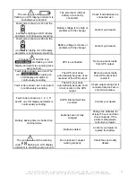
The icon 

 and 


flashing on LCD display and alarm is 

sounding every second. 

The external or internal 

battery is incorrectly 

connected. 

Check if all batteries are 

connected well. 

Fault code is shown as 27 and the 

icon 

 is lighting on LCD display 

and alarm is continuously sounding. 

Battery voltage is too high or 

problem with the charger. 

Contact your dealer. 

Fault code is shown as 28 and the 

icon 

 is lighting on LCD display 

and alarm is continuously sounding. 

Battery voltage is too low or 

problem with the charger. 

Contact your dealer. 

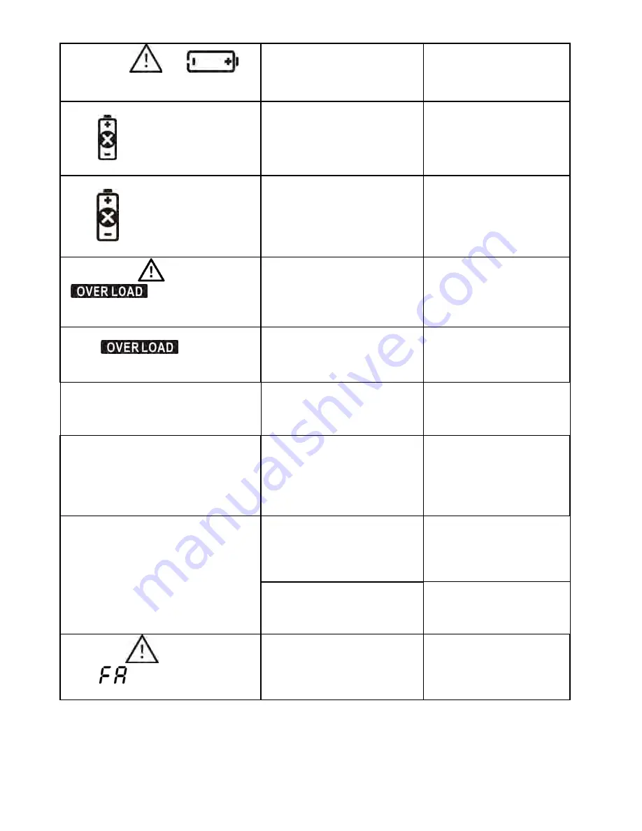
The icon 

 and the icon 


are flashing on LCD 

display and alarm is sounding twice 

every second. 

UPS is overloaded. 

Remove excess loads 

from UPS output. 

Fault code is shown as 43 and The 

icon 


is lighting on 

LCD display and alarm is 

continuously sounding. 

The UPS shut down 

automatically because of an 

overload at the UPS output. 

Remove excess loads 

from UPS output and 

restart it. 

Fault code is shown as 14 and alarm 

is continuously sounding. 

The UPS shut down 

automatically because short 

circuit occurs on the UPS 

output. 

Check output wiring and if 

connected devices are in 

short circuit status. 

Fault code is shown as 1, 2, 3, 11 

and 41 on LCD display and alarm is 

continuously sounding. 

A UPS internal fault has 

occurred. 

Contact your dealer 

Batteries are not fully 

charged. 

Charge the batteries for 

at least 5 hours and then 

check capacity. If the 
problem still persists, 

consult your dealer. 

Battery backup time is shorter than 

nominal value 

Batteries defect. 

Contact your dealer to 

replace the battery. 

The icon 


and the warning 

code 

 flashing on LCD display 

and alarm is sounding every second. 

Fan is locked or doesn’t 

working properly. 

Check fans and notify 

dealer. 


Содержание E3 LCD RT IEC 1000

Страница 1: ...800 1000 1500 S 2000 2500 S 3000 3500 S VA User guide ________________________3 Notice d utilisation ________________20 ...

Страница 2: ...INFOSEC UPS SYSTEM 4 rue de la Rigotière 44700 Orvault FRANCE www infosec ups com Hot Line Tel 33 0 2 40 76 15 82 Fax 33 0 2 40 94 29 51 hotline infosec fr 10 10 AA 59 203 03 2 English Version ...

Страница 3: ...ting and call the hot line 1 2 Connected products Combined UPS and connected equipment leakage current should not exceed 3 5 mA Make sure that the connected load does not exceed UPS capabilities To ensure improved backup time and longer battery life we recommend a load equivalent to 1 3 of nominal power Do not plug the UPS input into its own output socket Do not plug the UPS into a power strip or ...

Страница 4: ...sonnel who take the necessary precautions Keep unauthorized personnel away from batteries A battery can present a risk of electric shock and cause short circuits The following precautions should be observed by the qualified technician Remove watches rings or other metal objects from hands Use tools with insulated handles Disconnect the charging source prior to connecting or disconnecting battery t...

Страница 5: ... use 2 1 Rear panel view E3 LCD RT IEC 800 1000 1500 S 2000 2500 S E3 LCD RT IEC 3000 3500 S E3 LCD RT NEMA 800 1000 1500 S 2000 E3 LCD RT NEMA 2500 S E3 LCD RT NEMA 3000 3500 S 1 Programmable outlets connect to non critical loads 2 Output receptacles connect to mission critical loads 3 AC input 4 Input circuit breaker 5 Network Fax Modem surge protection 6 Emergency Power Off function connector E...

Страница 6: ...t connecting battery wires Before installing the UPS please follow the steps below to re connect battery wires Step 1 Step 2 Step 3 Remove front panel Connect the AC input and re connect battery wires Put the front panel back to the unit Rack mount installation Step 1 Step 2 Tower installation Step 1 Step 2 Step 3 2 3 Setup the UPS Step 1 UPS input connection Plug the UPS into a two pole three wir...

Страница 7: ... port and the other to the communication port of your PC With the monitoring software installed you can schedule UPS shutdown start up and monitor UPS status through PC The UPS is equipped with intelligent slot perfect for either SNMP or AS400 card When installing either SNMP or AS400 card in the UPS it will provide advanced communication and monitoring options PS USB port and RS 232 port can t wo...

Страница 8: ...acement NOTICE This UPS is equipped with internal batteries and user can replace the batteries without shutting down the UPS or connected loads hot swappable battery design Replacement is a safe procedure isolated from electrical hazards CAUTION Consider all warnings cautions and notes before replacing batteries Note Upon battery disconnection equipment is not protected from power outages Step 1 S...

Страница 9: ... errors occur Up selection key Press this button to display previous selection in UPS setting mode Switch to UPS self test mode Press and hold ON MUTE buttons for 5 seconds to enter UPS self testing while in AC mode OFF ENTER button Turn off the UPS Press and hold this button at least 2 seconds to turn off the UPS Confirm selection key Press this button to confirm selection in UPS setting mode SEL...

Страница 10: ... in pie chart Indicates the backup time in numbers H hours M minute Warning fault information Indicates that warning and fault occur Indicates the warning and fault codes codes are listed in details page 14 Setting operation Indicates the setting operation Battery info Load info Input output and battery info UPS status Warning fault info Setting operation Backup time info Load info UPS status Back...

Страница 11: ...t circuited UPS status Indicates that programmable management outlets are working Indicates that the UPS alarm is disabled Indicates the UPS powers the output directly from the mains see details page 13 Indicates that the battery charger is working see details page 13 Indicates that the UPS is working in boost mode see details page 13 Indicates that the UPS is working in buck mode see details page...

Страница 12: ...ontents Meanings ENA Enable DIS Disable ESC Escape EP EPO FA Fan TP Temperature CH Charger RAC Rack display TOE Tower display SF Site Fault 3 5 UPS setting There are two parameters to set up the UPS Parameter 1 Program alternatives There are 4 programs to set up output voltage setting programmable outlets enable disable programmable outlets setting LCD display direction and exit Parameter 2 Settin...

Страница 13: ...esents output voltage is 208 Vac 220 presents output voltage is 220 Vac 230 presents output voltage is 230 Vac 240 presents output voltage is 240 Vac 2 Programmable outlets enable disable Interface Setting figures ENA Programmable outlets enable DIS Programmable outlets disable 3 Programmable outlets setting Interface Setting figures Setting the backup time limits in minutes from 0 999 for program...

Страница 14: ...unction Then press Enter button again to confirm the setting Step 4 Press the Up button ON MUTE again to switch to 03 of program list Then press Enter button for setting programmable outlet time Push Up button to change the value of backup time according your demand Then press Enter to confirm the setting Step 5 Press Up button ON MUTE to switch to 00 of program list Then press Enter button to exi...

Страница 15: ...er than low loss point the boost AVR will be activated Battery mode When the input voltage is beyond the acceptable range or power failure and alarm is sounding every 4 seconds UPS will backup power from battery Standby mode UPS is powered off there is no output supply power but the batteries can be charged 3 7 Faults reference code Fault event Fault code Icon Fault event Fault code Icon Bus start...

Страница 16: ...ding every second 4 T R O U B L E S H O O T I N G If the UPS system does not operate correctly please solve the problem by using the table below Symptoms Possible causes Remedy The AC input power is not correctly connected Check if input power cord firmly connected to the mains No indication and alarm even though the main is normal The AC input is connected to the UPS output Plug AC input power co...

Страница 17: ...ess loads from UPS output Fault code is shown as 43 and The icon is lighting on LCD display and alarm is continuously sounding The UPS shut down automatically because of an overload at the UPS output Remove excess loads from UPS output and restart it Fault code is shown as 14 and alarm is continuously sounding The UPS shut down automatically because short circuit occurs on the UPS output Check out...

Страница 18: ...viceable parts If the battery service life 3 5 years at 25 C ambient temperature has been exceeded the batteries must be replaced In this case please contact your dealer 5 2 Storage Before storing charge the UPS 5 hours Store the UPS covered and upright in a cool dry location During storage recharge the battery in accordance with the following table Storage Temperature Recharge Frequency Charging ...

Страница 19: ...INFOSEC UPS SYSTEM 4 rue de la Rigotière 44700 Orvault FRANCE www infosec ups com Hot Line Tel 33 0 2 40 76 15 82 Fax 33 0 2 40 94 29 51 hotline infosec fr 10 10 AA 59 203 03 19 Version française ...

Страница 20: ... puis contacter le Service Après Vente 1 2 Produits connectés La somme du courant de fuite de l onduleur et de l équipement connecté ne doit pas excéder 3 5 mA S assurer que la charge alimentée n est pas supérieure à la capacité de l onduleur afin d assurer une plus grande autonomie et une plus longue durée de vie des batteries nous recommandons une charge égale au 2 3 de la puissance nominale Ne ...

Страница 21: ...n des batteries doit être effectuée par un personnel qualifié ayant une parfaite connaissance des précautions de sécurité Une batterie peut causer un choc électrique ou un intense court circuit Les précautions suivantes doivent être observées par le technicien lors de l intervention Retirer montres bagues Utiliser des outils à poignées isolées Débrancher l onduleur du secteur avant toute intervent...

Страница 22: ...00 S E3 LCD RT NEMA 3000 3500 S 1 Sorties programmables elles sont connectées aux sorties non essentielles 2 Prises de sortie elles sont connectées aux sorties essentielles 3 Prise d alimentation 4 Disjoncteur d entrée fusible thermique 5 Protection contre les surtensions réseau fax modem 6 Connecteur de fonction d arrêt d urgence EPO 7 Port de communication USB 8 Port de communication RS 232 9 Sl...

Страница 23: ... 15 82 Fax 33 0 2 40 94 29 51 hotline infosec fr 10 10 AA 59 203 03 23 Étape 1 Étape 2 Étape 3 Retirer la face avant Connecter l alimentation CA et reconnecter les câbles de batteries Replacer la face avant de l onduleur Montage en version rack Étape 1 Étape 2 Montage en version tour Étape 1 Étape 2 Étape 3 ...

Страница 24: ...S 232 et l autre extrémité au port de communication de l ordinateur Le logiciel de suivi étant installé il est possible de paramétrer depuis l ordinateur l arrêt et le redémarrage et aussi de contrôler l état de l onduleur 2 Slot intelligent L onduleur est équipé d un slot intelligent prévu soit pour une carte SNMP soit pour une carte AS400 L installation d une carte SNMP ou AS400 sur l onduleur p...

Страница 25: ...ur installer le logiciel de surveillance InfoPower CD livré avec l onduleur Après avoir installé le logiciel et redémarré l ordinateur l icône du logiciel InfoPower prise orange s affichera dans la zone de notification près de l horloge 2 4 Remplacement des batteries REMARQUE Cet onduleur est équipé de batteries internes que l utilisateur peut remplacer sans arrêter l onduleur ou les charges conne...

Страница 26: ...ON MUTE pendant au moins 2 secondes pour mettre l onduleur en marche Mise en sourdine de l alarme lorsque l onduleur est en mode batterie appuyer sur ce bouton pendant au moins 5 secondes pour activer ou désactiver l alarme sonore Ceci ne s applique pas lorsque des avertissements ou des alarmes se présentent Touche de contrôle haut Appuyer sur ce bouton pour afficher la sélection précédente dans l...

Страница 27: ...r l onduleur en mode Configuration uniquement lorsque l onduleur est à l arrêt Touche de contrôle bas Appuyer sur ce bouton pour afficher la sélection suivante dans le mode Configuration de l onduleur 3 2 Panneau LCD 1 Affichage en version rack 2 Affichage en version tour Info niveau des batteries Info niveau de charge en sortie Info Entrée sortie et batteries État de l onduleur Avertissement et i...

Страница 28: ...u la tension des batteries V tension Hz fréquence Indique le nombre de batteries externes connectées Informations sur la charge Indique la plage en pourcentage du niveau de charge 0 25 26 50 51 75 et 76 100 Indique une surcharge Indique une charge ou une sortie de l onduleur en court circuit État de l onduleur Indique que les sorties programmables fonctionnent Indique que l alarme sonore de l ondu...

Страница 29: ... abréviations de l écran LCD Abréviations Contenu de l affichage Significations ENA Activé DIS Désactivé ESC Sortie EP EPO FA Ventilateur TP Température CH Chargeur RAC Affichage en version rack TOE Affichage en version tour SF Défaut site 3 5 Configuration de l onduleur Deux paramètres permettent de configurer l onduleur Paramètre 1 Différents choix de paramétrage tension de sortie activation dés...

Страница 30: ... tension de sortie de 208 VAC 220 donne une tension de sortie de 220 VAC 230 donne une tension de sortie de 230 VAC 240 donne une tension de sortie de 240 VAC 2 Activation désactivation des sorties programmables Interface Configuration n 2 ENA active les sorties programmables DIS désactive les sorties programmables 3 Configuration des sorties programmables Interface Configuration n 3 Réglage de l ...

Страница 31: ...er le réglage Étape 4 Appuyer sur le bouton Up ON MUTE pour passer à 03 sur la liste des programmes Appuyer ensuite sur le bouton Enter pour régler l autonomie des sorties programmables Appuyer sur le bouton Up pour changer la valeur de la durée de secours selon les besoins Appuyer ensuite sur Enter pour confirmer le réglage Étape 5 Appuyer sur le bouton Up ON MUTE pour passer à 00 sur la liste de...

Страница 32: ...est activé Mode Boost lorsque CA est normal Lorsque la tension d entrée est au dessous de la plage de régulation de tension mais supérieure à la tension maximum l onduleur passe en mode AVR régulation automatique de tension et l amplificateur Boost est activé Mode Batteries Lorsque la tension d entrée est au delà de la plage acceptable ou lorsqu une panne de courant se produit l alarme sonore se d...

Страница 33: ... x Température trop élevée 41 x Tension onduleur élevée 12 x Surcharge 43 Tension onduleur basse 13 x 3 8 Indicateurs d avertissement Avertissement Icône clignotant Alarme Batteries faibles Alarme sonore toutes les secondes Surcharge Deux signaux toutes les secondes Les batteries ne sont pas connectées Alarme sonore toutes les secondes Surcharge Alarme sonore toutes les secondes Défaut alimentatio...

Страница 34: ... ou internes ne sont pas correctement connectées Vérifier que toutes les batteries sont correctement connectées Le code de défaut 27 est affiché l icône s allume sur l écran LCD et l alarme sonne en continu La tension des batteries est trop forte ou le chargeur est défectueux Contacter votre distributeur Le code de défaut 28 est affiché l icône s allume sur l écran LCD et l alarme sonne en continu...

Страница 35: ...est bloqué ou ne tourne pas correctement Vérifier les ventilateurs et contacter le distributeur 5 S T O C K A G E E T E N T R E T I E N 5 1 Indicateurs d avertissement Le système onduleur ne contient aucune pièce qui nécessite une intervention de la part de l utilisateur Les batteries doivent être remplacées lorsque leur durée de vie de 3 à 5 ans dans une température ambiante de 25 C a été dépassé...

Отзывы: