


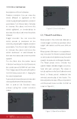


See Table 2 for common faults and troubleshooting methods.
7 Common Faults and Troubleshooting
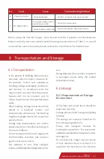
Table 2 Common Faults and Troubleshooting Methods
Return to the factory for repair.
Return to the factory for repair.
Return to the factory for repair.
Return to the factory for repair.
No power supply
No correct infrared
image
No serial
communication
available
Polarity inversion
failure
Failed
self-inspection
Damaged module
component
Improper serial cable
connection
Check if the power supply of the module
component is normal.
Check if the power supply of the module
component is normal.
Check whether the serial communication-
cable or interface connection is correct.
Check whether the serial communication
is normal.
Check whether the serial communication
is normal.
Return to the factory for repair.
Damaged module
component
Abnormal serial
communication
Damaged module
component
Damaged module
component
Abnormal serial
communication
Damaged module
component
No power supply
"Enhancement"
cannot be enabled
or disabled
normally
1
3
4
5
No.
Fault
Cause
Troubleshooting Method
2
English options. You can select based on your language preference. (There will be cues for
the separate language version, please contact the supplier for more language versions)
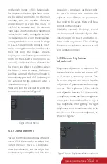
Angle display: enables you to enable or disable the display of azimuth, pitch angle, and roll
angle. When angle display is enabled, the azimuth is displayed on the upper part of the
screen, the pitch angle on the right part, and the roll angle on the lower part. The azimuth
is not displayed with a specific value, while the pitch and roll angles are. When the angle
display is disabled, the screen will not display any angle information.
Angle calibration: After a thermal imager is carried from the manufacturing site to a
different place, due to influences of local magnetic field and gravity, angle calibration must
be performed for its built-in angle module for a more accurate display of angles. After going
to the Angle calibration menu, operate by following the instructions on the screen. After
that, the system will perform angle calibration based on the collected information.
11
Tyke-L3
Operation and Maintenance Manual


