11
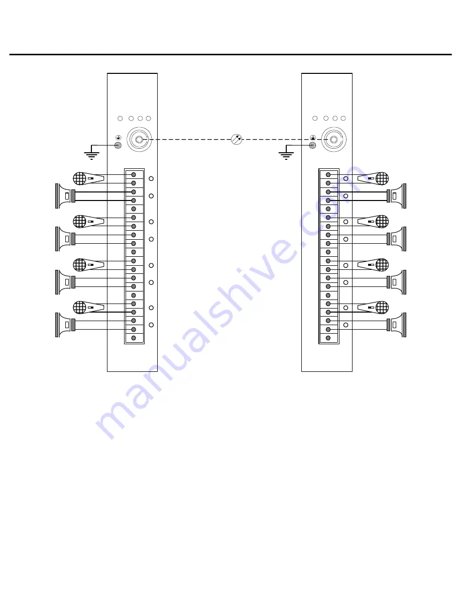
TYPICAL SYSTEM CONNECTION
PWR
1
2
3
4
5
6
7
8
9
10
12
13
14
15
16
17
18
19
20
OP
Fiber
Earthing
N3774XA-4
N3774XB-4
Figure 2. Typical application diagram
Страница 1: ...FIBER OPTIC TRANSMISSION SYSTEM N377 N357 SERIES LJLWDO 0XOWLSOH XSOH XGLR 7UDQVFHLYHU User Manual Infinova ...
Страница 2: ......
Страница 3: ...EIVER PANEL 6 N3774XA XB 1 M R N3574XA XB 1 M R 6 N3774XA XB 4 M R N3574XA XB 4 M R 7 N3774XA XB 8 M R N3574XA XB 8 M R 8 N3774XA XB 12 M R N3574XA XB 12 M R 9 AUDIO INPUT IMPEDANCE SETTINGS 10 TYPICAL SYSTEM CONNECTION 11 TRANSMISSION REPEATER 12 CABLE DIAMETER CALCULATION AND LIGHTNING SURGE PROTECTION 13 ...
Страница 4: ......
Страница 5: ...plied in accordance with good engineering practices and that products are proved by our examination to be defective This warranty does not extend to any Infinova products which have been subject to acts of accident misuse abuse neglect improper application or installation improper operation or maintenance connection to an improper voltage supply or to materials which have been altered or repaired ...
Страница 6: ...ach transmitter or receiver incorporates status indicators for monitoring of proper system operation The modules are available in either stand alone or card unit versions Stand alone module Card unit The N3774 series are compatible with 9 125micron single mode fibers the N3574 series are compatible with 50 125 or 62 5 125micron multimode fibers Transceiver N3774XA is compatible with transceiver N3...
Страница 7: ...uplex factory selectable audio transceiver module card N3774XA 8 M R Digital 8 duplex factory selectable audio transceiver module card N3774XB 8 M R Digital 8 duplex factory selectable audio transceiver module card N3774XA 12 M R Digital 12 duplex factory selectable audio transceiver module card N3774XB 12 M R Digital 12 duplex factory selectable audio transceiver module card INSTALLATION Installa...
Страница 8: ...ITS WHENEVER POSSIBLE INSTALL IN EVERY OTHER SUBRACK Forced air cooling with N3910 000 POWER SUPPLY Power supply for card unit The N3774 and N3574 card unit is powered by a plug in power supply that is provided with the appropriate desk chassis or EIA 19 subrack Power supply for stand alone module The N3774 and N3574 card unit can be converted into a stand alone module when installing into proper ...
Страница 9: ... supply Connection Diagram Note When the series is powered together with other devices cameras and etc by a single 24VAC power source please make sure that the related device has a full wave bridge rectifier circuit ...
Страница 10: ...2 13 14 15 16 17 18 19 20 OP Power on indicator red Optical link loss indicator red Chassis GND Optical port FC or ST CH1 Audio input indicator green CH1 Audio output indicator green 1 1 Audio channel Refer to table 1 for detailed pin assignments for audio Earthing for loss indicator ...
Страница 11: ...dio input indicator green CH1 Audio output indicator green CH2 Audio input indicator green CH2 Audio output indicator green CH3 Audio input indicator green CH3 Audio output indicator green CH4 Audio input indicator green CH4 Audio output indicator green 1 2 3 4 1 Audio channel 2 Audio channel 3 Audio channel 4 Audio channel Refer to table 1 for detailed pin assignments for audio Earthing for loss ...
Страница 12: ...dio channel Refer to table 1 for detailed pin assignments for audio PWR 1 2 3 4 5 6 7 8 9 10 11 12 13 14 15 16 17 18 19 20 Optical link loss indicator red Optical port FC or ST CH5 Audio input indicator green CH5 Audio output indicator green CH6 Audio input indicator green CH6 Audio output indicator green CH7 Audio input indicator green CH7 Audio output indicator green CH8 Audio input indicator gr...
Страница 13: ...channel Refer to table 1 for detailed pin assignments for audio PWR 1 2 3 4 5 6 7 8 9 10 11 12 13 14 15 16 17 18 19 20 Optical link loss indicator red Optical port FC or ST CH9 Audio input indicator green CH9 Audio output indicator green CH10 Audio input indicator green CH10 Audio output indicator green CH11 Audio input indicator green CH11 Audio output indicator green CH12 Audio input indicator g...
Страница 14: ...input impedance Jumper for setting CH2 Audio input impedance Jumper for setting CH3 Audio input impedance Jumper for setting CH4 Audio input impedance Figure 1 Audio jumper locations For detailed jumper setting and pin assignments please refer to table 1 Table 1 Audio input impedance setting and pin assignments references Note In table 1 Pin 1 denotes the pin with the MINIMUM number of each audio ...
Страница 15: ...YSTEM CONNECTION PWR 1 2 3 4 5 6 7 8 9 10 11 12 13 14 15 16 17 18 19 20 OP PWR 1 2 3 4 5 6 7 8 9 10 11 12 13 14 15 16 17 18 19 20 OP Fiber Earthing Earthing N3774XA 4 N3774XB 4 Figure 2 Typical application diagram ...
Страница 16: ...signal received from transmitter and sends it to receiver By using a N3951 the transmission distance of the system is doubled Typical application connection PWR 1 2 3 4 5 6 7 8 9 10 11 12 13 14 15 16 17 18 19 20 OP PWR 1 2 3 4 5 6 7 8 9 10 11 12 13 14 15 16 17 18 19 20 OP Fiber Earthing Earthing N3774XA 4 N3774XB 4 O U T I N Fiber N3951 Figure 3 Transmission repeater ...
Страница 17: ... shall be 0 8000mm A lower diameter value tends to cause voltage loss and even system instability 0 8000 1 000 1 250 2 000 10 283 86 451 137 716 218 1811 551 20 141 42 225 68 358 109 905 275 30 94 28 150 45 238 72 603 183 40 70 21 112 34 179 54 452 137 50 56 17 90 27 143 43 362 110 60 47 14 75 22 119 36 301 91 70 40 12 64 19 102 31 258 78 80 35 10 56 17 89 27 226 68 90 31 9 50 15 79 24 201 61 100 ...
Страница 18: ...e Use shielded cables or thread the cables through metal tubes for burial thus to ensure the electric connection to the metal tube In case it s difficult to thread the cable through the tube all the way it s acceptable to use tube threaded cables only at both ends of the transmission line yet the length in burial should be no less than 15 meters The cable sheath and the tube should be connected to...
Страница 19: ......
Страница 20: ...51 Stouts Lane Monmouth Junction NJ 08852 U S A Tel 1 888 685 2002 toll free USA 1 732 355 9100 Fax 1 732 355 9101 E mail sales infinova com V2 1312 ...