background image

16 

LT6387 Iss 4 (05/14) 


880 FL Users Instructions


SECTION FOUR Basket Fuel Bed Cleaning and Layout. 


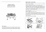
Place the Long Thin log as shown, making sure not to obstruct the Pilot Assembly.


Position the last shape as shown, making sure it does not obstruct the Pilot Assembly.


Place a single layer of Beige Bark Chips onto the Airtray and a few Narrow Chippings under the 

front of the basket as shown to finish the Fuel Bad layout. 


Do not fit the remaining  three Shapes !


Содержание 880FL

Страница 1: ...NSTRUCTIONS FOR STANDARD FIRE CAST BASKET Please read these instructions carefully before you start installing or using this appliance Keep this booklet handy for future reference This appliance is fo...

Страница 2: ...Fitting 9 SECTION FIVE General 17 INSTALLATION INSTRUCTIONS SECTION SIX Appliance Data 19 SECTION SEVEN Regulations and Warnings 20 SECTION EIGHT Siting the Appliance Flue Class1 21 SECTION NINE To I...

Страница 3: ...cleaning the coals or cleaning after servicing installation it is recommended that it be of the type fitted with a HEPA filter Disposal of refractory ceramic materials To keep dust to a minimum these...

Страница 4: ...r The Building Regulations Northern Ireland and The Current I E E Wiring Regulations if appropriate In IE Ireland the appliance must be installed by a competent person and installed in accordance with...

Страница 5: ...lit by pressing key the operational mode is switched from manual to Room Thermostat setting and vice versa When Room Thermostat mode is active the display shows the set temperature value and the AUTO...

Страница 6: ...ressed key at least for 5 seconds the temperature unit changes from Celsius to Fahrenheit degrees and vice versa Battery level indication Handset When the batteries have to be changed in the handset t...

Страница 7: ...ill overheat if fitted incorrectly when fitting the batteries ensure that they are fitted as per the marking on the rear of the holder i e minus of battery against spring e Once the new batteries are...

Страница 8: ...clean the glass panel of your 880 FL We recommend you use a Ceramic hob cleaner these are available for all leading super markets i e ASDA TESCO SAINSBURY S Etc Brands of hob cleaning we have tested a...

Страница 9: ...h great care The moulded shapes may be removed for cleaning They can be brushed very gently with a soft brush to remove dust or any deposits A vacuum cleaner may only be used after the loose component...

Страница 10: ...Layout Make sure that the cross Lighting port are keep clear of any obstruction Place the 2 log shapes along the front edge of the burner top plate Place a single layer of small bark chippings along t...

Страница 11: ...structions SECTION FOUR Fuel Bed Cleaning and Layout Continued Place the 2 log shapes along the rear of the air tray assembly Position a single layer of bark chippings along the front edge of the air...

Страница 12: ...12 LT6387 Iss 4 05 14 880 FL Users Instructions SECTION FOUR Fuel Bed Cleaning and Layout Continued Place the 2 log shapes as shown Place the 2 log shapes as shown...

Страница 13: ...OUR Fuel Bed Cleaning and Layout Continued 880FL Users Instructions SECTION FOUR Basket Fuel Bed Cleaning and Layout Centralise the Basket into the fire over the Two rivets in Fire Box Position the Tw...

Страница 14: ...Position the Two rear shapes as shown Position the Two Front shapes as shown Place a single layer of the small black bark chippings on the burner making sure to leave roughly a 5mm gap between them an...

Страница 15: ...Iss 4 05 14 880FL Users Instructions SECTION FOUR Basket Fuel Bed Cleaning and Layout Position 2nd L H shape as shown Place the Thick Middle shape as shown so it rests on the top of the front R H shap...

Страница 16: ...wn making sure not to obstruct the Pilot Assembly Position the last shape as shown making sure it does not obstruct the Pilot Assembly Place a single layer of Beige Bark Chips onto the Airtray and a f...

Страница 17: ...the inspection covers located on the back and top of the outer firebox This can be obtained by doing the following 880 FL Users Instructions SECTION FIVE General Points Continued Remove the two side c...

Страница 18: ...firebox Taking care not to damage the top liner remove the two fixing screw from the top of the inner firebox Carefully pull the inner firebox forward to clear the outer firebox assembly Remove the in...

Страница 19: ...460 Mk 580 Oxy pilot 9079 N G 9079 N G Gas Connection 8mm compression semi rigid or rigid Data Badge Location Located on the bottom left hand side of the appliance behind the trim and fascia Battery...

Страница 20: ...ent Office IN IE Ireland The appliance must be installed by a competent person and installed in accordance with the current edition of I S 813 Domestic Gas Installation the current building regulation...

Страница 21: ...ppliance or if it is a new installation Note A brick or stone chimney with a 125 mm 5 ins minimum diameter flue liner conforming to BS 715 may be used Provided a suitable sealing plate is fitted to th...

Страница 22: ...between vertical sides of combustible surround should not be less than 875 mm provided fire is central to the surround and sides do not project more than 150 mm When vertical side forward projection i...

Страница 23: ...d onto the firebox assembly and retained using the six off M4 nuts provided Remove the gas connection cover located within the burner shelf left hand side and connect to the restrictor elbow provided...

Страница 24: ...he valve carrier Place the Burner Assembly into the Cast Assembly making sure not to trap any wires leads and screw down with the original 3 x screws Position the E D B on the underside of the Basket...

Страница 25: ...t be less than 502mm from the centre of the firebox The horizontal stud work should not be less than 764mm from the base of the firebox This will ensure 50mm minimum clearance from the sides and 110mm...

Страница 26: ...he fault corrected if the fault cannot be corrected disconnect the fire from the gas supply and seek expert advice Spillage can be caused by a restriction in the flue system down draught or insufficie...

Страница 27: ...cuum cleaner nozzle taking care not to damage the pilot head TO REMOVE THE BURNER TRAY BASKET Remove RH and LH side covers undo glass fixing Remove glass panel Remove the loose fuel bed components Dis...

Страница 28: ...Undo the Injector tip with a spanner Only remove the injector TIP Refit the injector Tip and retighten with a spanner NOTE The other Injector needs to be left with the appliance or customer Refit the...

Страница 29: ...mpression nut on the supply pipe at the pilot Carefully pull off the ignition lead Disconnect the thermocouple at the end of the main control valve Remove the cross headed nut holding the pilot to the...

Страница 30: ...date and supported by receipts in each case 5 This warranty is not transferable and relates to the original installation only 6 The Registration Form must be correctly filled out and returned 7 The ap...

Страница 31: ...OUR DETAILS Name ________________________________ Address ________________________________ Post Code TELEPHONE No PRODUCT DETAILS Model 880 FL Serial No Date of Purchase This information can be found...

Страница 32: ...32 LT6387 Iss 4 05 14...

Страница 33: ...ate of First annual service Engineer Name Gas Safe Registration No Date of Second annual service Engineer Name Gas Safe Registration No Date of Third annual service Engineer Name Gas Safe Registration...

Страница 34: ...34 LT6387 Iss 4 05 14...

Страница 35: ...35 LT6387 Iss 4 05 14...

Страница 36: ...36 LT6387 Iss 4 05 14...

Страница 37: ...37 LT6387 Iss 4 05 14...

Страница 38: ...38 LT6387 Iss 4 05 14...

Страница 39: ...39 LT6387 Iss 4 05 14...

Страница 40: ...w Rate Inj tip Restrictor Plate 6255 1 X Bag of Black Chippings 6462 Inlet Cover 6251 Fireplace Frame 6257 Glass Panel 6248 Air Tray 6258 Silicone Sealing Strip 4818 x 2 C Cell Battery 12 Remote Contr...

Отзывы: