User guide
25 of 45
V 1.0.1
2021-01-27
REF-AIRCON-C302A-IM564 user guide
Air conditioner application reference design kits
System design
The REF-AIRCON-C302A-IM564 reference design’s motor current sensing is a direct AD sample, which
means the output of RS2 shunt resister is send to AD directly, with R83, R77 and C51 to provide sensing bias
and LPF.
R76 and C33 is a low pass filter for IM564’s local hardware OCP, 1 ~ 3 µs time constant is recommended.
VFO of IM564 (pin 14) is a multi-function pin, which means it is:
-
an analog output pin for IPM temperature sensing to IMC302A’s AD pin (net of IPM_Temp, with LPF
of R70 and C35)
-
a digital output pin for motor gatekill to IMC302A’s GK pin (net of IPMGATEKILL, with LPF of R115
and C56)
3.2
PFC section of REF-AIRCON-C302A-IM564
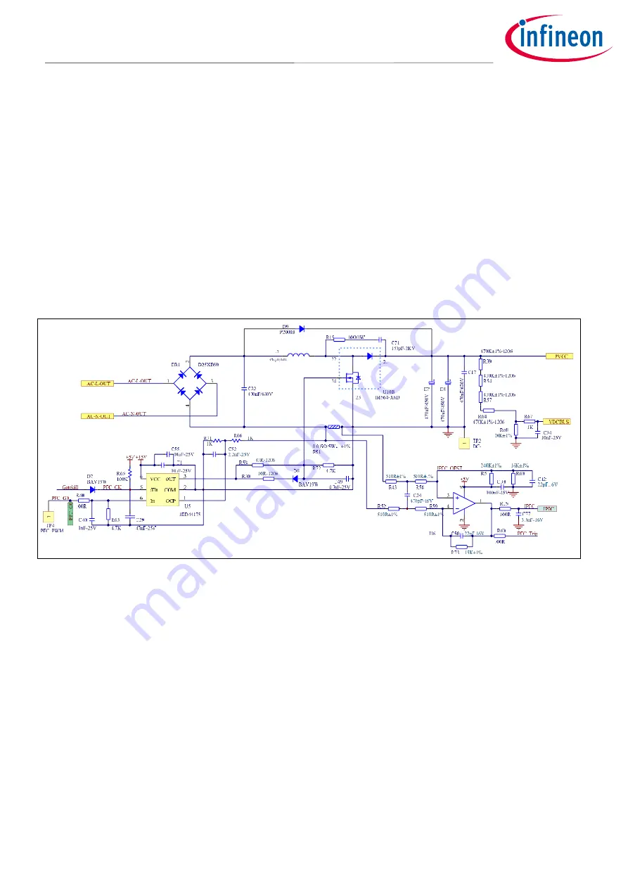
Figure 21 provides the PFC MOSFET driver and current sensing details.
Figure 21
Schematics for PFC driver and current sensing
A 1ED44175 used for PFC MOS drive and PFC overcurrent protection.
-
R66 & R71 select the threshold of 1ED44175’s OCP; default setup is 33.3 A
PEAK
which is 150% ~ 200%
of IMC302A’s internal OCP threshold
-
C52, R66 & R71 is the low-pass filter of hardware OCP, 1 ~ 2 µs time constant is recommended
-
C49, R30 & R53 select the PFC MOSFET switching du/dt; trade-off between switching noise and
power loss is required
-
D7 sends the fault output of 1ED44175 to IMC302A’s GK pin, so that the motor can stop
immediately at the PFC overcurrent condition. Please remove D7 if IMC302A’s system control
software already handles the PFC OCP and restart related sequence.
The bypass diode D9 is designed to withstand in-rush current during an abnormal power-up, and to
withstand repetitive pulse-charge current when the motor is running and the PFC is off. In the absence of
this diode, the excessive in-rush current or pulse-charge current that exceeds the specification of
maximum input current is likely to damage the IPM diode.


