


C-COM Satellite Systems Inc.
Page 88 of 164
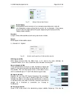
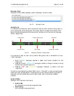
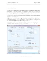
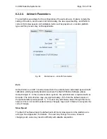
Fig. 71:
Deploy Antenna Input Values
Quick Deploy
Automatically moves antenna to the manually entered Elevation, Azimuth
and Polarization angles without first moving to 30˚ on Elevation. This process
moves to the set angles without the extra angle tuning that occurs with the
Deploy Antenna button.
Duration
Length of time of Manual Movement using increments of 30ms
Speed
Motor Speed of Manual Movement
3 = Slowest, 9 = Highest
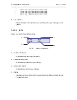
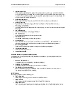
Fig. 72:
Duration and Speed Input for Manual Movements
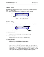
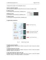
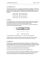
DVB Signal (0-255)
DVB Signal received from the DVB Tuner. A “U” next to the value indicates an
“unlocked” status. An “L” next to the DVB value indicates locked signal.
Beacon Signal (0-100)
If the optional beacon receiver is used, the Beacon Signal will
appear in this area along with the power density received from
the satellite. This will only appear when a lock status occurs
which is indicated by an “L” next to the beacon signal value.
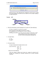
RF Signal (30-120)
Displays the real time RF Signal throughout the acquisition
process. A value of 30 that is flashing Red and or Yellow
indicates the LNB is not being powered sufficiently, or there is
an issue with the coax cable connection. Some Ka services will
display 70 if threshold is overridden (i.e. Tooway &
SurfBeam2).
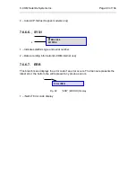
RF Threshold (30-75)
Used in RF mode search for determining proper satellite frequency. This can be


