


O
PERA
T
I
ON
G
B
20
Service Manual
Ne
w
E
lectronic Cold Platform 2005
Edition
2005.03.25
Language
E
nglish
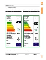
ALARMS MANAG
E
M
E
NT:
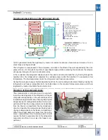
Alarms serve to notify the user of specific conditions such as: prolonged opening of fridge door; excessive
temperature in freezer compartment.
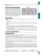
Door Open Alarm:
I
f the fridge door is kept open for a time longer than that defined by a parameter set in EEPROM memory,
an audible signal is emitted and the fridge lamp flashes at regular intervals. Close the door to reset the
alarm.
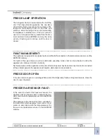
Freezer Compartment Temperature Alarm:
There are two types of alarms that can be generated if the freezer compartment temperature rises exces-
sively:
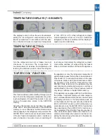
Alarm A1:
I
n this case it is still possible to recover the food in the freezer by cooking it immediately and either consum-
ing it or re-freezing it once cooked. LEDs 3 and 5 flash on the appliance control panel to indicate the
presence of the alarm, while a beeper signal is emitted at the same time.
Alarm A2:
I
n this case the food in the freezer compartment must be discarded. LEDs 3, 4 and 5 flash on the appliance
control panel to indicate the presence of the alarm, while a beeper signal is emitted at the same time.
I
n alarm status the appliance inhibits all functions or adjustments to force a specific operating mode with
specific On/ Off thresholds that set the freezer compartment temperature to given values in relation to the
type of alarm (A1 or A2); the new On / Off thresholds for the two alarm types are parameterised in the
EEPROM memory. During alarm status forced defrost cycles are executed, activated once the number of
hours parameterised in the EEPROM memory have elapsed, as in normal operation. To reset the alarm and
restore normal operation, the appliance must be set to LOG
I
CAL OFF (freezer knob set to minimum).
The beeper can be muted by opening and closing the refrigerator door. When alarm status is reset the
timer-controlled defrost cycles are deactivated, but if the alarm reset occurs during a defrost cycle, the
alarm is reset but the current defrost cycle continues to its natural conclusion.
I
f the appliance is set to
logical OFF with A1 or A2 active, and then switched on again after a fixed number of minutes as parameterised
in the EEPROM memory, a defrost cycle is forced after which the appliance will resume operation in ac-
cordance with the settings that were present before the alarm.
Once the appliance has entered alarm status it is not possible to quit except by means of a reset procedure
(the only possible change is the transition from alarm A1 to alarm A2).
I
n the event of a power failure, the
state present at the time of interruption is resumed when power is restored.
Control of freezer compartment temperature, performed by means of the freezer air temperature sensor, is
executed continuously during appliance operation.
I
n the event of a freezer air sensor fault, the alarms will
no longer be displayed.
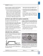
Temperature control does not start for a time parameterised in the EEPROM memory from the first power-
on of the appliance, thus avoiding the possible occurrence of alarms during the testing phases at the first
power-on at the user’s home.
When the appliance is ON, the temperature control is inhibited for a given time interval parameterised in the
EEPROM memory in order to give the compartment time to cool without generating any superfluous alarms.
After a mains power failure the freezer compartment temperature is checked immediately, since prolonged
absence of electrical power is the main cause for heating of the appliance.


