background image

E

n

4

Language

English

s

E

r

vic

E

ability

Service Manual

Yate Production Dryers

Edition

2006.09.21

3.

  Press the Anti-crease button (start of programme)

   The Anti-crease icon (start of programme) and the drying icon light up

   The heating element warms to low (half) heat


Check the low heat temperature

4.

  Press the Delayed Start button

   The display shows 1h and delayed start

5.

  Press the Alarm button - the Alarm icon and the Cooling cycle icon light up

   The heating element warms to full heat


Check the full heat temperature

6.

  Press the 

Timer

 button; the drying time blinks in the display


7.

  Press the 

Crease Care (end of programme)

 button.

   The option icons light up and the status icons for 

Crease Care (end of programme)

   The drum rotates counterclockwise, the heating element switches off and the buzzer sounds

   If the drum stops turning after 3 seconds and the display reads END, there is a problem with the con-

ductivity sensor or the magnetic connector is not coupled.


Open the door and check the interlock microswitch; counterclockwise rotation ceases

8.

  Close the door - the display reads 

ON

9.

  Press the button to select the Wool programme

   Check that the 

Clean filter and water tray empty

 icons are alight

   Check that the display reads 

Time remaining

   Check that the 

wool

 icon is displayed

10.

Press the button to select the 

Synthetics

 programme

   Check that the 

Iron - hanger - Cupboard

 icons are displayed

   Check that the 

full heat 

icon is displayed

   Check that the 

Synthetics

 icon is displayed

11.

Press the button to select the 

Cotton - Low heat

 programme

   Check that the 

Low heat

 icon is displayed

   Check that the 

Cotton

 icon is displayed

12.

Press the button to select the 

Cotton - full heat programme

   Press  the 

  Set  &  forget

  option  button  repeatedly  Check  that  the  drying  indicator  progresses  from 

Cupboard

 to 

hanger

 to 

Iron

, and back to 

Cupboard

13.

Press the button to select the 

Iron Less

 programme

   Check that the 

Iron Less icon is displayed

14.

Press the button to select the 

Cooling cycle

 programme

   Check that the 

Cooling cycle

 icon is displayed

15.

Press the button to select the 

Delicate

 programme

   Press the 

Start/Cancel

 button to run the drying programme

   When the status icons light up, press the 

Start/Cancel

 button to end the programme

   Check that the display reads 

88:88

 momentarily

16.

Press the 

ON-Off

 button to switch off the dryer

faults and remedies

NOTE: when a fault occurs, the door interlock Led blinks rapidly (frequency > 1 hz, i.e. several times 

per second) [INDESIT machines]

when a fault occurs, the On/Off Led blinks rapidly (frequency > 1 hz, i.e. several times per second) 

[AqUARIUS machines]

Содержание AS60VEX

Страница 1: ...cument are the property of Indesit Company S p A All rights reserved This document and the information it contains are supplied with no acceptance of liability deriving from possible errors or omissions Furthermore no part may be reproduced used or disclosed except where authorized in writing or in accordance with a contractual clause ...

Страница 2: ...support document for technical personnel It contains a description of the various product types and their operating principle and provides indications on serviceability Service technicians should always consult the specific model on www servicenet indesitcompany com to find data and updates of wiring diagrams technical bul letins and spare parts ...

Страница 3: ...mmes Electromechanical vented dryer 24 3 COMPONENTS 25 3 1 Electronic condenser and vented dryers 25 3 2 Electromechanical condenser and vented dryers 30 4 WIRING DIAGRAMS 32 4 1 Indesit electromechanical vented models 32 4 2 Ariston electromechanical vented models 34 4 3 Vented models with sensing brush 36 4 4 Vented models with sensing strip 36 4 5 Condenser models with sensing brush 38 4 6 Cond...

Страница 4: ...tion 2006 09 21 1 PRODUCT TYPE 1 1 PRODUCT LEGEND A Ariston S Scirocco Project L LED 7 7 kg 0 second digit V Vented Market I Indesit D Display 6 6 kg indicates a possible G 0 Electromechnical update C Condenser A S D 7 0 C EX Vented models Condenser models 1 2 PRODUCT STRUCTURE ...

Страница 5: ...full The indicator will stop blinking a few seconds after the empty tray has been replaced for this to occur the dryer must be in operation see Controls The Clean Filter icon reminds the user to clean the filter each time the dryer is used see Maintenance section The On Off indicator confirms that the dryer is in operation or ready for selection of a program me ON OFF button with the dryer in oper...

Страница 6: ...neces sary 8 To select the option of a warning beep at the end of the programme press ALARM 9 Press the START button to run the program me The display gives an indication of the time re maining During operation the door can be opened to allow the removal of clothes that have already dried leaving the remainder to dry further Ha ving closed the door the START button must be pressed again for the dr...

Страница 7: ...d for this to occur the dryer must be in operation see Controls The On Off indicator confirms that the dryer is in operation or ready for selection of a programme If this indicator blinks there is a fault in the machine see Fault finding ON OFF button with the dryer in operation pressing this button will stop the cycle and shut off the machine Pressing the button again the machine restarts The Pro...

Страница 8: ...timer delayed start The Drying Guide is a simple table indicating the relationship between different fabrics and the loading capacity of the drum The TIMER knob is used to set the interval of time that must elapse before the start of a delayed drying programme Turn the knob clockwise to set the desi red length of time number of hours before the dryer is to start to go back simply turn the knob cou...

Страница 9: ...t 143 C Single phase with start capacitor 2 pole 2800 rpm 7µF X Condenser system ISL70CNL Electronic control and LED interface C 72 dBA H 850 mm W 595 mm D 584 mm Weight 41 kg 7 kg 12 hours 3 hour steps Push Push 2300W 230V Resettable thermostat 106 C One shot thermostat 143 C Single phase with start capacitor 2 pole 2800 rpm 7µF X Condenser system AS60VEX Rx Lx rotation End of pro gramme alarm C ...

Страница 10: ...ell as driving two fans mounted coaxially with the motor shaft The front fan draws in cold air from outside the ma chine and directs it into the condenser The rear fan blows air through the heating elements and into the drum The drum rotates clockwise and counterclockwise in alternation the alternating sequence is programmed electronically or timed electromechanically When the drum rotates counter...

Страница 11: ...The condenser is equipped with two seals stuck longitudinally to the top and the bottom right hand side so that hot air from the drum and cool air drawn in from outside by the front fan will not come into contact Water produced by condensation of the steam is directed into the pump reservoir located at the rear of the machine and forced from here into the collection tray at the top of the machine ...

Страница 12: ...e a float to trip a microswitch generating a FAULT signal used by the mainboard to deactivate the heating elements 7 10 11 Microswitch 12 Float 13 Overflow hole 12 Should the user forget to empty the tray water will spill eventually through an overflow in the tray holder From here the water is returned to the pump reservoir where the level will then rise and ultimately trip the float switch 11 13 ...

Страница 13: ...nto the drum is controlled by two sensors NTC front and rear which monitor the temperature during the cycle and inform the mainboard The drying quality and times are governed by a conductivity sensor that interacts with the two NTC sen sors and informs the mainboard as to the level of moisture and how far the fabrics have dried during the programme 14 One shot thermostat 15 Cold air inlet 16 Heate...

Страница 14: ...converts the moisture to steam From here the steam passes through a filter located in the bottom part of the door seal and is vented to the atmosphere by way of a duct 2 1 3 8 5 4 6 7 2 2Venteddryingcycleandcirculationofair steam water electromechanical 1 Filter and steam outlet from drum 2 Steam venting duct 3 Cold air inlet 4 Holes admitting hot air to drum at rear 5 Heating elements 6 Vent outl...

Страница 15: ...g on the selected cycle automatic programmes When the set point temperature is detected by the sensor one heating element will be deactivated The final 10 minutes of the programme are allo cated to cooling the fabrics Indesit machines have just one self resetting thermostat that will deactivate both heating elements when the temperature reaches 78 C and reactivate them when the temperature drops T...

Страница 16: ...e moisture content drops the temperature at the front of the drum approaches the temperature at the rear This calculation is repeated every 40 seconds approx The conductivity sensor to which an input current is applied at 5 Vdc measures the moisture content of the load by way of a sensing strip wired to the GND connection on the mainboard The control module compares the resistance with a known ref...

Страница 17: ...emperature by way of the switch and the selected duration of the programme is controlled by the timer At the start of the programme the heating element is on and the temperature controlled by the thermostat positioned on the front air duct which will pilot one half of the heater to cut in and out as necessary until the moment when the timer switches to the cooling stage The operating temperatures ...

Страница 18: ...splayed Automatic option is available if you change your mind 3 Select any Options if required 4 Press the Start button Brief programme approximately 10 minutes that softens fibres of clothing that is ready for ironing This is not a drying programme see previous page Options available Alarm 1 Press the Easy Iron button 2 Select Alarm option if required 3 Press the Start button Synthetics Dries you...

Страница 19: ...at the condensate tray is empty before setting a delayed start To set the timer press the delayed start button the display reads OFF and the DELAYED START icon lights up Pressing the button a section time a delay of one hour is selected and the display reads 1 hr Pressing the button again another hour is added to the delay Pressing the button when the display reads 18 hr the message OFF appears an...

Страница 20: ...ay should fill up during the course of a programme the heater switches off and the dryer activates a Cooling step In this situation the icon blinks and the buzzer will sound At this point the dryer stops all the progress icons light up and the empty water icon blinks The tray must now be emptied and the machine restarted otherwise the clothes will not dry After restarting the dryer a few seconds w...

Страница 21: ...AMMES knob on 3 2 Select any options if required 3 Press the START button Options available Alarm Delayed Start Pre Creasecare Post Creasecare 1 Position the PROGRAMMES knob on 1 2 Select any options if required 3 Press the START button Options available Alarm High Heat Delayed Start Pre Creasecare Post Creasecare Consult suggested drying times see Laundry The last 10 minutes of these programmes i...

Страница 22: ...nd the indicator alongside the button will light up together with the 3 hour delay indicator Pressing the button a second time the delay increases to 6 hours the 3 hour indicator will go out and the 6 hour indicator will light up Each time the delay setting button is pressed the delay increases by 3 hours as shown by the corresponding indicator If the 12 hour delay indicator is alight pressing the...

Страница 23: ...intenance section Opening the door If the door is opened with a programme in progress the dryer will stop and the following situation is crea ted The 3 hour delay indicator and all 3 progress indicators light up During a delay period the delay will continue to count down The START button must be pressed to reinstate a delay programme One of the delay indicators will blink to to indicate the curren...

Страница 24: ...mme can also be used for average loads if you prefer a damper result Timed Drying up to 120 minutes Dries wet clothes that will be ironed Acrylic fibres or small loads less than 1kg Consult suggested drying times see Laundry Always allow the dryer to complete this phase This is the programmes final phase Approximately 10 minutes before the finish the knob advances automatically to the Cool Tumble ...

Страница 25: ... and interacts with the two NTC sensors to compute the time remaining Readings occur every 40 approx Traps any threads and fluff shed by the tumbled fabrics To be cleaned after every cycle The rear fan draws in air from the room and blows it onto the heating elements Rear fan vented dryer Draws in air from outside to cool the condenser this turns the steam in the condenser to water Installed only ...

Страница 26: ...r with screws Air is directed through channels in the chassis The heating elements temperature controls thermistors and rear guard are supplied as an assembly and have a 5 way connector provi ding the interface with the electronics The coils of the heater unit make up one top element and one bottom element The bottom element is rated 1100 watts static and receives its full power input permanently ...

Страница 27: ...d conducti vity sensor to compute the cycle time remaining The rear NTC sensor middle is mounted to the heater unit above the heating element between the one shot and resettable thermostats This sensor is used by the electronics to control the temperature at the rear of the dryer SAFETY THERMOSTATS 1The non resettable one shot thermostat whi te spot is a safety device that disconnects all loads at...

Страница 28: ... deactivate one heating element then closes to reactivate the element when the temperature drops Front thermostats Location of ECO Energy Save thermostats The drum is composed of a galvanized front section a rear section and two removable plastic paddles The rear section of drum is pierced to admit the flow of air The back of the drum is carried by a shaft that turns in a friction bearing incorpor...

Страница 29: ...ray is full and must be emptied before the heating elements can come into operation again The motor is a two pole type running at 2800 rpm Protection is guaranteed by a bimetal thermal overload cutout that resets automatically and may disconnect the electrical power input to the windings A start capacitor rated 7 µF is installed alongside LED or LCD the mainboard is located behind the control pane...

Страница 30: ... wiring diagram it can be seen that when this switch is activated the heater unit is acti vated on either full or half power delivering 2200W or 1100W output To select maximum heat the switch is positioned in to select minimum heat the switch is positioned out The door interlock relay is installed on the power PCB located at the back of the control panel The power PCB always has a single pole rela...

Страница 31: ...ermostats are mounted in the front part of the air duct In ARISTON dryers and in certain INDESIT mo dels the settings are 55 C full load 60 C half load INDESIT vented models have one thermostat only set to open at 58 C INDESIT condenser models have one thermostat only set to open at 78 C When the critical temperature registers the thermo stat deactivates one heating element for the duration of the...

Страница 32: ...00 C3 C1 C2 12 MAIN TIMER SEqUENCE REVERSINg TIMERS PROGRAMME CAM Timer Markings 160 140 120 100 80 60 40 20 10 Actual time 163 160 143 122 102 81 61 41 20 12 10 switch switch no 336 330 294 252 210 168 126 84 42 24 21 1 2 3 4 5 6 7 8 9 10 11 12 13 14 15 16 17 18 19 20 21 22 23 24 25 26 27 28 29 30 31 32 33 34 35 36 37 38 39 40 41 42 43 44 45 46 47 48 49 50 51 52 53 54 55 56 57 58 timer motor 2 1 ...

Страница 33: ... 8 A1 2 B1 5 B12 C2 4 B9 10 C3 3 B11 C1 2 B1 A2 10 A11 B5 A9 A10 B3 BROWN WHITE N 2 3 1 BLUE RELAY BLACK WHITE BLUE WHITE BLACK CYCLING THERMOSTAT ORANGE UPPER HEATER LOWER ORANGE ONE SHOT CUT OUT BROWN HEAT SWITCH ENERGY SAVE THERMOSTAT BLUE WHITE GREY BLUE WHITE BLUE CAPACITOR TIMER RED BROWN M BLUE ORANGE BROWN PB PB MOTOR WITH PROTECTOR DOOR SWITCH BROWN WHITE BLUE WHITE BLUE INSULATOR M MALE ...

Страница 34: ...NT SWITCHED MAX CURRENT Invensys EC Elbi 5000 C3 C2 C3 C4 16 4 A TIMER MOTOR 1A C3 C1 C3 C5 16 4 A TIMER MOTOR 1A A1 A3 A4 B3 B4 16 4 A MOTOR HEATER 10A B3 B4 B1 A4 A5 16 4 A HEATER 9 2A B9 B10 B11 B1 B2 16 4 A BUZZER 1A 3 140 mins 130 mins 120 mins 110 mins 100 mins 90 mins 80 mins 70 mins 60 mins 50 mins 40 mins 30 mins 20 mins 7 5 mins 1 2 3 4 5 6 7 8 9 10 11 12 13 14 15 16 17 18 19 20 21 22 23...

Страница 35: ...ART SWITCH PB PEAPSA ZBN 8 4 3 5 CUT OUT ONE SHOT BLUE BLUE M M PB PB CAPAC ITOR M A1 A0 RED BROWN BLUE MOTOR WHITE BROWN ORANGE BLUE A BROWN WHITE MAINS CONNECTION WITH SUPPRESSION L N E BLUE WHITE DOOR SWITCH BROWN WHITE TM REVERS G TIMER GREY BLUE M M WHITE GREY BLUE UPPER LOWER HEATER CYCLING STAT ORANGE BROWN ORANGE BLACK WHITE GREY GREY BLUE WHITE WHITE HEAT SWITCH BUZZER SWITCH BLACK 541272...

Страница 36: ...D Spade terminal E Motor with overload cutout F One shot thermostat G Resettable thermostat H Upper and lower heating elements I NTC sensor J Door switch K Connection to a c supply with suppressor L Sensing brush M Drum assembly 4 3 Vented models with sensing brush 5 4 3 2 1 2 1 3 2 1 J12 J3 J9 4 3 2 1 5 4 3 2 1 J11 J10 J4 2 1 A B C F G D H M I L J E K E N L ...

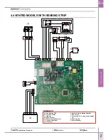
Страница 37: ...C Capacitor D Spade terminal E Motor with overload cutout F One shot thermostat G NTC sensor H Upper and lower heating elements I Door switch J Connection to a c supply with suppres sor K Sensing strip L Drum assembly 5 4 3 2 1 2 1 5 4 3 2 1 3 2 1 J12 J10 J4 J3 J9 2 1 4 3 2 1 J11 A B C F G D H I L J E E N L K 4 4 Vented models with sensing strip ...

Страница 38: ...nsor C Float switch D Pump E Capacitor F Motor with overload cutout G Spade terminal H One shot thermostat I Resettable thermostat J Upper and lower heating elements K NTC sensor L Connection to a c supply with sup pressor M Door switch N Sensing brush O Drum assembly 5 4 3 2 1 2 1 2 1 4 3 2 1 5 4 3 2 1 3 2 1 J11 J12 J10 J4 J3 J9 J5 4 3 2 1 J12 A B C F G D H I L J E E N L K N O M ...

Страница 39: ... B Front NTC sensor C Float switch D Pump E Capacitor F Motor with overload cutout G Spade terminal H One shot thermostat I NTC sensor J Upper and lower heating elements K Door switch L Connection to a c supply with sup pressor M Sensing strip N Drum assembly 5 4 3 2 1 4 3 2 1 2 1 5 4 3 2 1 3 2 1 J12 J10 J4 J3 J9 J5 4 3 2 1 2 1 J11 A B C F G D H I L J E E N L K N M ...

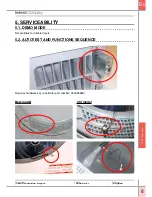
Страница 40: ...ility Service Manual Yate Production Dryers Edition 2006 09 21 5 SERVICEABILITY 5 1 DEMO MODE Not available for tumble dryers 5 2 Autotest and functions sequence Requires hardware key to activate part number C00095669 Old model New model ...

Страница 41: ...ing elements switch off and the buzzer sounds Check opposite rotation of motor and deactivation of heating elements If the drum stops turning after 3 seconds there is a problem with the conductivity sensor or the magnetic connector is not coupled 5 Open the door and check Counterclockwise rotation ceases and the clean filter Led lights up Check the door microswitch 6 Close the door turn the select...

Страница 42: ...light Check that the display reads Time remaining Check that the Wool icon is displayed 10 Press the button to select the Synthetics programme Check that the Iron Hanger Cupboard icons are displayed Check that the Full Heat icon is displayed Check that the Synthetics icon is displayed 11 Press the button to select the Cotton Low Heat programme Check that the Low Heat icon is displayed Check that t...

Страница 43: ...tton 4 Button 1 Button 2 Button 3 Button 4 Button 1 Button 2 Button 3 Button 4 Button 1 Button 2 Button 3 Button 4 Button 1 Button 2 Button 3 Button 4 Button 1 Button 2 Button 3 Button 4 Motor functions when it should not or motor does not get activated at all No motor action drum not turning Front NTC open or short circuit Pump triac welded closed Pump is working when it should not No pump action...

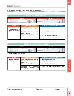
Страница 44: ... not get activated at all FAULT 01 MOTOR FAULT STATE INTERVENTION TO BE PERFORMED CORRECTIVE ACTIONS Refit the motor connection Change the wiring If not ok change the motor If there is not voltage replace the main board Check motor connections J3 on PCB Check continuity and state of the wiring J3 Check protector of the motor Check that there is voltage 220V on the pins 1 and 2 and 3 on the connect...

Страница 45: ...main board Valid only for condenser models FAULT 04 PUMP TRIAC WELDED CLOSED STATE INTERVENTION TO BE PERFORMED CORRECTIVE ACTIONS Pump is working when it should not If not ok replace the pump Clean and refit the connectors If not ok replace the wiring If not ok triac of the pump does not close replace the main board Check resistance continuity of the pump Check state of the connectors Check conti...

Страница 46: ...TIVE ACTIONS Eeprom is not pro grammed or not func tioning Unplug the machine wait for 2 min utes switch it ON and try it again Spare part main board removable eeprom Production main board welded eeprom If there is not replace one shot thermostat If there is not replace cycking thermostat If there is not replace heating element Clean and refit Replace the main board One shot open fault FAULT 10 ST...

Страница 47: ...odels FAULT 11 STATE INTERVENTION TO BE PERFORMED CORRECTIVE ACTIONS f the machine starts ok Clean and refit Change the wiring Replace the main board Replace the display board Display board does not manage to communicate with FAULT 12 STATE INTERVENTION TO BE PERFORMED CORRECTIVE ACTIONS No communication be tween display board and main board Unplug the machine wait for 2 min utes switch it ON and ...

Страница 48: ...should be about 500 kOhms in room temperature Check state of the connectors Check continuity and state of the wiring Triac in cort circuit replace the main board Upper heater relay welded closed FAULT 15 STATE INTERVENTION TO BE PERFORMED CORRECTIVE ACTIONS Upper resistance is ON even when it is not driven Replace the main board Master relay welded This fault appears after 20 minutes FAULT 17 STAT...

Страница 49: ...Check if the drum has got off the wheels during the transit Possible with the S N s before the 8th of October 2004 added in production the drum support pads Noise INTERVENTION TO BE PERFORMED CORRECTIVE ACTIONS C Scraps on inner rear panel louvre s S N before the 15th of November 2004 Clearance between drum and inner panel substitute the inner rear panel with the C00113861 which has 3mm segment re...

Страница 50: ... rear panel modified to reduce slot size by 1mm to prevent play between inner rear and base From the 19h of October 2004 Part code C00113038 V Drum scraping on inner rear panel motor sump Section of inner rear motor sump height reduced to increase clearance between drum and motor sump Part code C00112158 V Rubbing rear panel Introduction of modified side panels and IPR to provide additional cleara...

Страница 51: ...crews required for the blanking pieces fitted to the front panel and door liner door kit part code C00141611 Check the door switch Dead INTERVENTION TO BE PERFORMED CORRECTIVE ACTIONS C Adrift from the jockey pulley or broken caused by the jockey wheel movement S N before the 19th of October 2004 improve the bearing plastic moulding fitment substituting with the part code C00113879 C Off or broken...

Страница 52: ... the cable tie is used to hold a group of cable together C Micro lever sticking S N before the 17th of May 2005 add the stop feature to float pin to prevent over travel part code C00113884 C Microswitch lever sticking S N before the 15th of August 2005 increase height of pump and float cover guide legs by 3 5mm part code C00113893 C S N before the 15th of August 2005 change the door microswitch br...

Страница 53: ...t distortion Part code C00112143 Door Seal S N is before the 19th of January 2005 INTERVENTION TO BE PERFORMED CORRECTIVE ACTIONS C Add new Cable Clip Strengthening Ribs To IRP Clips Part Code C00113887 S N is before the 26th of January 2005 Pump cover becoming adrift INTERVENTION TO BE PERFORMED CORRECTIVE ACTIONS C Addition of corner brace to improve left hand side panel fit The brace is secured...

Страница 54: ...al introduced to improve the position of the seal on the airduct and ensure all backing tape is easily removed Part code C00141600 Felt Seal S N is before the 11th of April 2005 Lint built up INTERVENTION TO BE PERFORMED CORRECTIVE ACTIONS V Larger diameter front bearing seal introduced to ensure backing fully removed prior to application substitute felt seal with part code C00141600 S N is before...

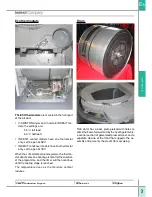
Страница 55: ...LECTRONIC CONDENSER DRYER COMPONENTS 1 Remove the 2 screws securing the top to the rear panel 3 Slide the panel back to free it from the lugs at the bottom Side panels 2 Slide the top back and lift 1 Remove the top 2 Remove the screws securing the side panel to the rear panel on certain dryers there is a screw under the base ...

Страница 56: ...to the side panels 2 Remove the water tray Remove 2 screws on the left of the control panel securing it to the tray holder Remove 1 screw on the right securing the control panel to the side restraint 3 Ease the control panel out releasing the three clips Led PCB and display PCB 1 Remove the top and control panel and disconnect the PCB Remove the PCB from the control panel ...

Страница 57: ...the Rx panel Detach the cowl from the front fan so that the PCB is able to pass Remove the 2 fixing screws at the front 1 Remove the top Lower the plinth and remove 2 Detach the front panel undoing the screws as illustrated 3 Detach the front fan freeing it from the guard Belt 1 Detach the top sides and control panel ...

Страница 58: ...e the 4 hex bolts behind the rear fan which secure the motor to the base This will slacken the drive belt 7 Remove the rear bearing 8 Draw back the rear panel so that the drum shaft can be freed from the panel then proceed to slide the belt back and remove it from the drum 9 At this point it will be possible to remove the air duct and lower the drum freeing the belt ...

Страница 59: ...ir duct 3 Remove the duct from the socket at the bottom this operation is made easier by laying the ma chine on its back 4 The front NTC sensor can be removed from the top part of the front air duct 5 The door microswitch can be removed 6 The front panel cannot be detached without first removing the air duct 1 Remove the top and control panel ...

Страница 60: ... 2006 09 21 2 Raise the drum and remove the air duct Air duct 1 Remove the top control panel side panels front panel and motor Front bearings 1 Detach the air duct 2 Replace the 4 bearings Rear bearing 1 Remove the guard of the rear bearing 2 Undo the screw securing the bearing assembly ...

Страница 61: ... 3 Release the reservoir from the base Rx and Lx 4 Replace the pump switch or float Pump switch and float 1 Remove the Lx side panel 3 To replace the heating element first disconnect the power cable from the mainboard Heater unit safety thermostats NTC sensors 1 Remove the guard from the heater unit 2 Disassemble the unit undoing the two screws securing it to the guard ...

Страница 62: ...the 4 bolts 2 Detachthefrontfans removingtherelativeguard the mainboard must be removed 3 Detach the rear fan 5 Lift the motor from the base slip off the belt and remove the tension idler Drum assembly Disassembly 1 Top 2 Side panels 3 Control panel 4 Front panel 5 Air duct 6 Rear bearing 7 Detach motor 8 Remove drive belt 9 The drum can now be separated from the rear panel ...

Страница 63: ...tches 1 Detach the control panel and remove the two screws securing the angle bracket 3 Detach the two timers undoing the screws that secure them to the bracket b Removal of door microswitch 1 Remove the left hand side panel 3 Remove the switch from the inside of the front panel 2 Release the clip holding the switch block to the front panel 2 Release the two clips on the PCB and unplug the connect...

Страница 64: ...he front panel and air duct can be removed This done it will also be possible to remove the door seal and the front bearings 2 Removethe5screwssecuringthefrontpaneltothebase and the four screws joining the panel and the air duct d Removal of motor 1 Detach the right hand side panel 2 Remove the rear guard of the heater unit and fan 3 Remove the rear fans undoing the three bolts that secure them to...

Страница 65: ... side panels 2 Detach the front panel and air duct 3 Detach the motor 4 Remove the belt from the front of the drum g Removal of ECO thermostats 1 Detach the front panel and air duct the two ECO thermostats are installed alongside the air duct 4 Release the motor by undoing the two front bolts and the rear bolt securing it to the mounting 5 Having separated the belt from the shaft the motor can be ...

Страница 66: ...2006 09 21 h Removal of drum reversing timer f Removal of drum 1 Complete all steps necessary in order to remove the belt 2 Remove the rear belt and separate the drum shaft from the rear panel the drum can now be removed from the casing 1 Undo the two screws securing the timer to the base ...

Страница 67: ...EL 103 AS60VEX TIMER KNOB 105 AS60VEX DELAY KNOB 107 AS60VEX BUTTON 111 HEAT SWITCH 112 START SWITCH 113 TIMER 114 BUZZER SWITCH 115 POTENTIOMETER 125 AS60VEX TOP 145 AS60VEX PCB 147 AS60VEX START BUTTON 148 AS60VEX BUTTON 149 TIMER MOUNTING PLATE 150 AS60VEX LIGHT GUIDE PRG 6 9 SDJH 7DYROH AS60VEX Service Manual Yate Production Dryers Edition 2006 09 21 ...

Страница 68: ...T PANEL WHITE 210 FRONT PANEL WHITE 211 THERMOSTAT WHITE LIGHT 212 DOOR SEAL 213 BEARING SHOE 215 MICROSWITCH DELAY 215 MICROSWITCH DELAY 221 AS60VEX DOOR FRAME 222 DOOR SURROUND 223 AS60VEX DOOR GLASS 223 DOOR GLASS SEAL 224 AS60VEX DOOR HINGE 228 AS60VEX DOOR HANDLE 233 DOOR CATCH 257 AS60VEX AIR DUCT ASSEMBLY PRG 6 9 SDJH 7DYROH Service Manual Yate Production Dryers Edition 2006 09 21 ...

Страница 69: ...6 LOCKING PIN 427 EARTH CLIP 427 M3 X 6 SCREW 428 REAR MOUNTING 429 FLANGE VENTING HOSE 429 FLANGE VENTING HOSE 432 THERMOSTAT KIT ONE SHOT CYCLING 442 CABLE GLAND 445 POWER CABLE 448 NOISE FILTER 448 SCREW 450 AS60VEX SIDE PANEL 450 6X3 8 SCREW 452 COVER REAR BEARING 452 6X3 8 SCREW 455 AS60VEX USER INSTRUCTION BOOK 463 CRADLE DRYER DRUM 464 2 2 KW HEATING ELEMENT HOUSING 464 HEATER HOUSING 464 2...

Страница 70: ... PANEL WHITE 125 8X1 2 SCREW 125 ALE70CFR TOP 154 ASD ADE70C DISPLAY LENS 157 CONTROL PANEL PCB 160 LX FUNCTION BUTTONS 161 RX FUNCTION BUTTONS 162 TOP PROGRAMME BUTTONS 163 BOTTOM PROGRAMME BUTTONS 164 ON OFF BUTTON 165 START BUTTON 166 ASD70CEX TRAY HANDLE 167 PROGRAMME LIGHT GUIDE ASD70CEX PRG 6 SDJH 7DYROH Service Manual Yate Production Dryers Edition 2006 09 21 ...

Страница 71: ...EW 343 8X1 2 SCREW 347 CATCH ALE70CFR PLINTH 349 SEAL ALE70CFR AIR DUCT 350 BEARING SHOE ASD70CEX PRG 6 SDJH 7DYROH 301 ALE70CFR OUTER DOOR WHITE 303 DOOR CATCH 303 DOOR CATCH 304 DOOR CATCH PLATE 305 BUSH 306 ALE70CFR MICROSWITCH LEVER 307 FILTER 310 ASD ADE70C PLINTH 311 8X1 2 SCREW 311 ALE70CFR FRONT PANEL 312 DOOR LATCH 312 DOOR LATCH 315 ALE70CFR TOP HINGE 316 ALE70CFR BOTTOM HINGE 317 DOOR C...

Страница 72: ...OD ONE SHOT CYCLING NTC 522 HEATER UNIT TOD ONE SHOT CYCLING NTC 526 CLIP 527 ALE70CFR FAN 533 BRUSH MOUNTING 533 SENSING BRUSH 538 SENSING STRIP INSULATION 539 SENSING STRIP 541 DRUM SHAFT 544 SCREW 544 NOISE FILTER 545 CRADLE DRYER DRUM 545 CRADLE DRYER DRUM 546 SENSING BRUSH MOUNT 547 ALE70CFR WATER TRAY HOLDER 548 ALE70CFR WATER TRAY 549 ELBOW ALE70CFR WATER TRAY 551 MAGNETIC CONNECTION KIT 55...

Страница 73: ...CAUS 623 BELT TENSION IDLER AND BRACKET 625 ALE70CFR MOTOR TYPE 350 626 BELT 632 FLOAT 632 FLOAT 633 FLOAT STEM 633 FLOAT STEM 634 ALE70CFR POMPA PTC 634 PUMP 635 ALE70CFR PUMP FLOAT COVER 635 SEAL PUMP FLOAT COVER 635 HORIZONTAL SPLASH GUARD 635 VERTICAL SPLASH GUARD 635 SEAL PUMP FLOAT COVER 636 CAP ALE70CFR HW KEY SOCKET 637 ALE70CFR CONDENSER 638 SEAL BASE CONDENSER Service Manual Yate Product...

Страница 74: ...ERS 101 ISL70CEX CONTROL PANEL 103 IS70VEX TIMER KNOB 107 ISL70CEX BUTTON 125 8X1 2 SCREW 125 WHITE TOP 147 ISL70CEX START BUTTON 152 ISL70CEX ON OFF BUTTON 153 LIGHT GUIDE 3 155 LIGHT GUIDE 4 157 CONTROL PANEL PCB 1 KNOB 166 ISL70CEX TRAY HANDLE PRG 6 SDJH 7DYROH Service Manual Yate Production Dryers Edition 2006 09 21 ...

Страница 75: ...ANEL 312 DOOR LATCH 312 DOOR LATCH 315 IS70CEX TOP HINGE 316 IS70CEX BOTTOM HINGE 317 DOOR CATCH PLATE 318 ALE70CFR DOOR SEAL 323 ALE70CFR MICROSWITCH 330 FRONT AIR DUCT 330 SENSING STRIP 330 FRONT AIR DUCT 332 6X3 8 SCREW 335 PLATE 335 GDA THERMOSTAT MOUNTING 335 FRONT THERMOSTAT 337 FRONT SEAL DRUM 340 ALE70CFR SIDE PANEL 340 6X3 8 SCREW 343 8X1 2 SCREW 347 CATCH ALE70CFR PLINTH 349 SEAL ALE70CF...

Страница 76: ...CLING NTC 522 HEATER UNIT TOD ONE SHOT CYCLING NTC 522 HEATER UNIT TOD ONE SHOT CYCLING NTC 526 CLIP 527 ALE70CFR FAN 533 BRUSH MOUNTING 533 SENSING BRUSH 538 SENSING STRIP INSULATION 539 SENSING STRIP 541 DRUM SHAFT 544 SCREW 544 NOISE FILTER 545 CRADLE DRYER DRUM 545 CRADLE DRYER DRUM 546 SENSING BRUSH MOUNT 547 ALE70CFR WATER TRAY HOLDER 548 ALE70CFR WATER TRAY 549 ELBOW ALE70CFR WATER TRAY 551...

Страница 77: ...D BRACKET 625 ALE70CFR MOTOR TYPE 350 626 BELT 630 ISL70CEX USER INSTRUCTION BOOK 632 FLOAT 632 FLOAT 633 FLOAT STEM 633 FLOAT STEM 634 ALE70CFR POMPA PTC 634 PUMP 635 ALE70CFR PUMP FLOAT COVER 635 SEAL PUMP FLOAT COVER 635 HORIZONTAL SPLASH GUARD 635 VERTICAL SPLASH GUARD 635 SEAL PUMP FLOAT COVER 636 CAP ALE70CFR HW KEY SOCKET 637 ALE70CFR CONDENSER 638 SEAL BASE CONDENSER 999 SHOE DRYING ACCESS...

Страница 78: ...esit Company viale Aristide Merloni 47 60044 Fabriano Italy tel 39 0732 66 11 telex 560196 fax 39 0732 66 2954 www indesitcompany com Language English Service Manual Yate Production Dryers Edition 2006 09 21 ...

Отзывы: