- 13 -
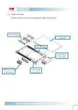
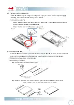
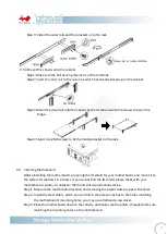
Step 4: Use hex screws from the accessories box to fix the motherboard in the chassis.
2.7
Connection Cable
2.2.1
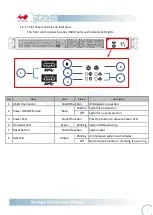
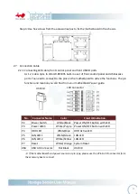
Connecting LED cable, front control panel and front USB IO ports
As 1.2.1 descripts, In Win IW-RF100S built-in a set of front control panel and USB access
ports. You need to connect to the pins on the motherboard to active the functions. The pin
function and location you can find from your motherboard’s user guide.
※
If the motherboard’s led power source is 3-pin type, please use the 2Pin-to 3Pin convertor form
the accessory box to connect.
No.
Connector Name
Color
Front IO Indication
P2
Power Switch
White/Black
Power ON/OFF Button with LED
P3
Power LED
※
White/Purple
Power ON/OFF Button with LED
P4
HDD LED
White/Blue
HDD Active LED
P5
LAN LED 1
White/Green
LAN LED
P6
LAN LED 2
White/Yellow
LAN LED
P7
Reset
White/Orange
System Reset
USB
USB 3.0 Connector
Flat Black
USB 3.0
USB 3.0
LED Connector
Содержание IW-RF100
Страница 1: ...IW RF100S User s Manual...


