


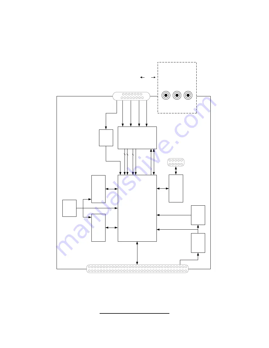
A functional block diagram of the VCE-PRO card is illustrated in
Figure 1.
FP
G
A
A
C
EX
EP
1K100
BGA-
2
5
6
SDR
A
M
4M
x32
BG
A-
90
SDR
A
M
4M
x32
BG
A-
90
Ph
ilips
SAA7115
Vi
d
e
o
Dec
oder
C
VBS0
/Y0
C
VBS1
/Y1
C0
Ca
rdBus
Conn
e
c
tor
6
8
-p
in
Fem
a
le
Y
8
8
3
i2
c
_
S
C
L
i2c
_
SD
A
Cr/
C
b
S
tr
obe
s
Cl
k
Co
nf
igu
ra
tion
EEPR
O
M
EPC
2
B
y
teB
last
er
Progra
m
min
g
H
ead
er
OS
C
66M
h
z
3
V
-t
o
-2.
5V
co
n
vert
e
r
S
o
ftS
ta
rt
32
-b
it
P
C
I
Ma
s
te
r/S
la
ve
Trig
ge
r
D
e
tect
o
r
15 Pin
Co
nne
ctor
( VC
E-
PR
O
-F
v
e
rs
ion )
C1
St
ereo
Ph
o
n
o
-J
acks
( VC
E-
P
R
O
v
e
rs
ion )
OR
Figure 1 – VCE-PRO Block Diagram
Page
8 of 44
Содержание VCE-PRO
Страница 5: ...Introduction This chapter outlines the key features of the Imperx VCE PRO card Page 5 of 44 ...
Страница 20: ...Using the VCE PRO This chapter contains information on how to configure and use the VCE PRO card Page 20 of 44 ...
Страница 38: ...Electrical Interfaces This chapter contains information on the VCE PRO s connectors Page 38 of 44 ...


