7
STVZSkW ed 09/08
VICTRIX ZEUS Superior kW I
Technical Documentation
Technical Documentation
2
1
4
3
5
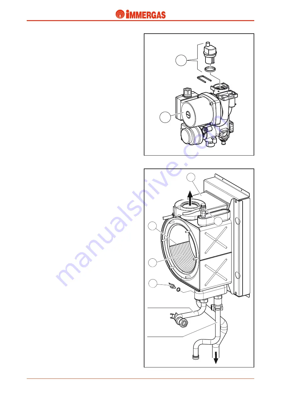
Boiler pump (1).
Operates on the primary circuit return immediately after the
3-way valve to which it is connected. It is part of the integrated
multifunction unit realised in composite material.
The pump leaves the factory with the speed set at "AUTO".
This means that the pump functions at three variable speed
in a way to keep the temperature difference between flow and
return constant.
There is a seat on the body where the automatic air vent valve
(2) is housed.
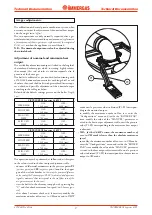
Primary heat exchanger
(condensation module).
It is formed by a casing that contains 4 (version 26 kW) and 5
(version 32 kW) coil-shaped elements.
Each element is made up from 5 elliptical spirals (3).
The entire module is realised in stainless steel and its internal
part makes up the sealed combustion chamber and the con-
densation chamber (2).
VICTRIX ZEUS Superior 26 kW I.
The first three elements are affected directly by the action of
the cylindrical burner applied to the front, while the fourth is
arranged in the condensation chamber, which is separated from
the combustion chamber by sheet steel (see flue circuit).
To reduce head losses to a minimum and increase the flow rate
available to the system, the flow is made up from the parallel
connection of the first two elements, the return instead, is made
up from the parallel connection of the last two elements.
VICTRIX ZEUS Superior 32 kW I.
The first four elements are affected directly by the action of
the cylindrical burner applied to the front, while the fifth is
arranged in the condensation chamber, which is separated from
the combustion chamber by sheet steel (see flue circuit).
To reduce head losses to a minimum and increase the flow
rate available to the system, the flow is made up from the
parallel connection of the first three elements, the return,
instead is made up from the parallel connection of the last
two elements.
For both versions, the heat exchanger inlet is connected to
the pump flow and the outlet, on which the NTC central
heating probe is positioned (1), is connected to the primary
circuit flow.
The primary circuit return and flow pipes are coupled using
threaded fittings with flat gasket.
The flue hood (4) is connected to the rear using a relevant
gasket blocked by a metal ring.
The condensate drain is also found in the lower part.
To ease the escape of any air bubbles still present in the coils,
there is a manual air vent in the upper part of the module
(5).
1
2
COMBUSTION
PRODUCTS
RETURN
FLOW
CONDENSATE
DRAIN
Содержание VICTRIX Superior 32 kW X
Страница 2: ......


