background image

49

INS

TALLER

U

SER

M

AINTEN

AN

CE

 TECHNI

CI

AN

TECHNI

CAL

 D

AT

A

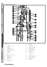
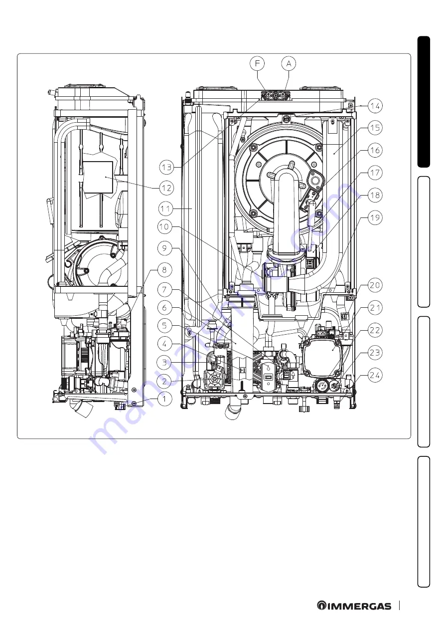
1.32  MAIN COMPONENTS

37

Key (Fig. 37):

-  System filling cock

-  3-way valve (motorised)

-  D.H.W. heat exchanger

-  D.H.W. probe

-  Gas valve

-  Condensate drain trap

-  D.H.W. flow switch

-  Manual air vent valve

-  Flow probe

10 

-  Air / gas mixer

11 

-  System expansion vessel

12  - Burner

13 

-  Sample points (air A) - (flue gases F)

14 

-  Flue probe

15 

-  Air intake pipe

16 

-  Ignition/detection electrode

17 

-  Condensation module

18  - Fan

19 

-  System pressure switch

20 

-  Return probe

21 

-  Boiler circulating pump

22 

-  3 bar safety valve

23  - By-pass

24 

-  System draining cock

Содержание VICTRIX OMNIA

Страница 1: ...Instructionsandrecommendations Installer User Maintenancetechnician 1 042016ENG 1 042016ENG IE VICTRIXOMNIA ...

Страница 2: ...ion 31 1 17 Concentricverticalkitinstallation 32 1 18 Separatorkitinstallation 35 1 19 C9adaptorkitinstallation 37 1 20 Ductingoffluesortechnicalslots 39 1 21 ConfigurationtypeB openchamberandfanassistedforindoors 40 1 22 Flueexhausttoflue chimney 40 1 23 Flues chimneysandchimneycaps 41 1 24 Watertreatmentplantfilling 42 1 25 Systemfilling 43 1 26 Fillingthecondensatedraintrap 43 1 27 Gassystemsta...

Страница 3: ...uetest 74 3 13 P C B programming 75 3 14 Solarpanelscouplingfunction 80 3 15 Chimneysweep function 80 3 16 Pumpanti blockfunction 80 3 17 Three wayanti blocksystem 80 3 18 Radiatorsantifreezefunction 80 3 19 P C B periodicalself check 80 3 20 Automaticventingfunction 81 3 21 Screedheaterfunction 81 3 22 Casingremoval 82 4 Technicaldata 83 4 1 Variableheatoutput 83 4 2 Combustionparameters 84 4 3 T...

Страница 4: ...ctionsandbyprofessionallyqualifiedstaff meaningstaffwithspecifictechnicalskills intheplantsector asprovidedforbyLaw ImproperinstallationorassemblyoftheImmergasdeviceand orcomponents accessories kitsanddevicescancauseunex pectedproblemsforpeople animalsandobjects Readtheinstructionsprovidedwiththeproductcarefullytoensureproper installation Thisinstructionsmanualprovidestechnicalinformationforinstal...

Страница 5: ...therequirementsofstandardUNIENISO9001 2015 ForfurtherdetailsontheproductCEmarking requestacopyoftheDeclarationofConformityfromthemanufacturer specifyingthe appliancemodelandthelanguageofthecountry Themanufacturerdeclinesallliabilityduetoprintingortranscriptionerrors reservingtherighttomakeanymodificationstoitstech nicalandcommercialdocumentswithoutforewarning ...

Страница 6: ...s WARNINGS Strictlyfollowalloftheindicationsnexttothepictogram Failuretofollowtheindicationscangeneratehazardsituations resultinginpossibleminorinjuriestothehealthofboththeoperatorandtheuseringeneral and orslightmaterialdamage ATTENTION Readandunderstandtheinstructionsoftheappliancebeforecarryingoutanyoperation carefullyfollowingtheinstruc tionsgiven Failuretoobservetheinstructionsmayresultinmalfu...

Страница 7: ...moval to outdoors in the place for loading and transporting the appliances and components as well as the eventual re placementofthosewithappliancesand orequivalentcomponents Thewallsurfacemustbesmooth withoutanyprotrusionsorrecessesenablingaccesstotherearpart Theyarenotdesignedto beinstalledonplinthsorfloors Fig 1 Byvaryingthetypeofinstallationtheclassificationoftheapplianceandprecisely TypeB23 or...

Страница 8: ...nottocompromise theappliance selectricalsafety Parag 2 9 2 10 Alwaysdisconnecttheappliancefromvoltageand dependingonthetypeofoperation decreasethepressureand orbringitto zerointhegasandDHWcircuits Iftheapplianceisconnectedtoalowtemperaturedirectzone itisnecessarytocheckthenecessaryflowrateandpossiblyadda relaunchpump Packing materials staples nails plastic bags polystyrene foam etc constitute a ha...

Страница 9: ...ination Installationofgasappliances flueexhaustpipesandcombustionairintakepipesisforbidden in places with a fire risk for example garages closed parking stalls and in potentially dan gerousplaces Donotinstallontheverticalprojectionofhobs Do not install in places rooms that constitute public areas of apartment buildings internal stairwaysorotherescaperoutes e g floorlandings entrancehalls etc Insta...

Страница 10: ...iesorsimilar choosea separateinstallationareathatensurescombustionairsupplythatisfreefromchemicalsubstances Makesurethecombustionairisnotfedthroughchimneysthatwerepreviouslyusedwithboilersorothercentralheatingappli ancespoweredbyliquidorsolidfuels Infact thesemaycauseanaccumulationofsootinthechimney Riskofmaterialdamageafterusingspraysandliquidstosearchforleaks Leakspraysandliquidsclogthereference...

Страница 11: ...ntandinadjoiningrooms Theinstallationroomsmustbepermanentlyventilated incompliancewiththelocalregula tionsinforce atleast6cm foreverykWofinstalledheatinput exceptintheeventofanyin creasesneededforelectro mechanicalvacuumcleanersorotherdevicesthatcouldputthein stallationroomundervacuum InstalltheappliancesinB23 andB53 configurationinnon residentialpremisesandwhicharepermanentlyventilated Failuretoc...

Страница 12: ...Condensatedrain minimuminter naldiameterØ13mm AC Domestichotwateroutlet G Gassupply AF Domestichotwaterinlet R Systemreturn 1 Boilerdirecthydraulicconnection 2 Wall mounted hydraulic connec tionwithImmergasDINtemplate Height mm Width mm Depth mm 738 400 247 CONNECTIONS GAS DOMESTICHOT WATER SYSTEM G AC AF R M 3 4 1 2 1 2 3 4 3 4 ...

Страница 13: ...13 Installer User Maintenance technician Technical Data 1 3 MINIMUMINSTALLATIONDISTANCES 3 Key Fig 3 A 450mm B 350mm C 30mm D 30mm E 350mm ...

Страница 14: ...Immergasappliancesresistethyleneandpropyleneglycolbasedantifreezeliquids ifthemixturesarepreparedperfectly Minimumtemperature 15 C Protectthedomestichotwatercircuitagainstfreezingbyusinganaccessorythatissuppliedonrequest antifreezekit comprisingtwo electricheatingelements therelevantwiringandacontrolthermostat carefullyreadtheinstallationinstructionscontainedintheac cessorykitpack Inthepreviouslyl...

Страница 15: ...tional Thenecessarypartsforthistypeofinstallation bracket mustalsobepurchasedseparatelyasoptionalkit Toinstallproceedasfollows Installthebracket 2 insidetherecessedframefixingitwiththescrews 3 inthepre drilledholes Fig 4 Wall mounttheboiler 4 byinsertingthehooksofthebracket 2 intherelativeseats Fig 5 Theboiler 4 isnowmountedinsidetherecessedframe 1 Fig 6 1 2 3 3 4 1 4 2 2 5 1 4 6 ...

Страница 16: ...ancecomesas optionalkit performtheconnectionsinaccordancewiththetypeofinstallationtobemadeandrespectingthearrangementshownin Fig 7 1 3 G V M AC R SC AF 2 7 Key Fig 7 V Electricconnection G Gassupply AC Domestichotwateroutlet AF Domestichotwaterinlet SC Condensatedrain minimuminternaldiameterØ13mm M Systemflow R Systemreturn 1 Systemfillingcock 2 Systemdrainingvalve 3 3 barsafetyvalvedrainfitting ...

Страница 17: ...dupstreamofeachconnectionbetweentheappli anceandthegassystem Thiscock ifsuppliedbytheappliance smanufacturer canbedirectlyconnectedtotheappliance i e downstreamfromthepipesconnectingthesystemtotheappliance accordingtothemanufacturer sinstructions TheImmergasconnectionunit suppliedasanoptionalkit alsoincludesthegascock whoseinstallationinstructionsarepro videdinthekit Inanycase makesurethegascockis...

Страница 18: ...schargingwastewaters Intheeventcondensateisnotdischargedintothewastewaterdrainagesystem acondensateneutralisermustbeinstalledtoensurecom pliancewiththeparametersestablishedbythelegislationinforce Atreatmentoftheheatingandwatersystemwaterisrequired incompliancewiththetechnicalstandardsinforce inordertoprotectthe systemandtheappliancefromdeposits e g scale slurryorotherhazardousdeposits Inordernotto...

Страница 19: ...ks c onthecover d 4 Removethecover d fromthecontrolpanel e Atthispoint itispossibletoaccesstheterminalboard f 1 a 3 c d b 2 c c 3 3 4 e f 8 Alsoensurethattheelectricalinstallationcorrespondstomaximumabsorbedpowerspecificationsasshownontheboilerdataname plate Theboilersaresuppliedcompletewitha Y typeH 05 VVF3 x 0 75 mm2 powersupplycable withoutplug Thepowersupplycablemustbeconnectedtoa230V 10 50Hzm...

Страница 20: ... neveruseadapters multiplesocketsorextensionleads Installationwithsystemoperatingatdirectlowtemperature Theboilercandirectlysupplyalow temperaturesystembysettingtheflowtemperatureadjustmentrange t0 and t1 Par 3 13 Inthis case itissuitabletoaddaspecificsafetykit optional madeupofathermostat withadjustabletemperature Thethermostatmustbepositionedonthesystemflowpipeatadistanceofatleast2metresfromthea...

Страница 21: ...n momentarilychangingthetemperatureoftheautomaticprogram Thechrono thermostatispoweredbytwo1 5VLR6typealkalinebatteries ComandoAmicoRemoto RemoteControlDevice V2 CARV2 withclimatechrono thermostatfunction In addition to the functions described in the previous point the CARV2 panel enables the user to control all the important information regardingoperationoftheapplianceandtheheatingsystemwiththeop...

Страница 22: ...ngjumperX40 MakesurethattheOn Offthermostatcontactisofthe clean type i e independentofthemainsvoltage otherwisetheP C B wouldbe damaged AnyComandoAmicoRemoto remotecontrol V2mustbeconnectedtoterminals44 40and41 eliminatingjumperX40ontheP C B Fig 40 Theboilercanonlybeconnectedtooneremotecontrol IftheComandoAmicoRemotoremotecontrolV2 oranyotherOn Offchrono thermostatisusedarrangetwoseparatelinesin c...

Страница 23: ...erature Theexternalprobealwaysoperateswhenconnected regardlessofthepresenceortypeofroomchrono thermostatusedandcanworkin combinationwithImmergaschrono thermostats Thecorrelationbetweensystemflowtemperatureandexternaltemperatureisdeterminedbythepositionofthecentralheatingselector switchonthedevicecontrolpanel orontheCAV2 controlpanelifconnectedtotheboiler accordingtothecurvesshowninthediagram Fig 1...

Страница 24: ...eResistanceFactorforindividualcomponentsisindependentfromthetypeofapplianceonwhichitisinstalledandhasadimension lesssize Itishowever conditionedbythetemperatureofthefluidsthatpassthroughthepipeandtherefore variesaccordingtoapplicationsfor airintakeorflueexhaust Eachsinglecomponenthasaresistancecorrespondingtoacertainlengthinmetresofpipeofthesamediameter theso calledequivalent length canbeobtainedf...

Страница 25: ...ternalduct Forsafetypurposes donoteventemporarilyobstructtheapplianceintake exhaustterminal Thevariouspartsofthefluesystemmustbecheckedtoensurethattheyhavebeenlaidinsucha wayastopreventthecoupledpartsfromdetaching inparticular theflueexhaustductinthe Ø80 separator kit configuration If the condition described above is not adequately guaran teed itwillbenecessarytousetheappropriateretainingclampkit ...

Страница 26: ...r R Equivalent length inmofconcentric pipeØ80 125 Concentricpipe80 125Øm1 2 1 1 90 concentricbend80 125Ø 3 0 1 4 Concentricbend45 Ø80 125 2 1 1 Terminalcompletewithconcentrichorizontalintake exhaust Ø 80 125 2 8 1 3 Terminalcompletewithconcentricverticalintake exhaust Ø 80 125 3 6 1 7 90 concentricbendØ80 125withinspection 3 4 1 6 StubpipewithinspectionØ80 125 3 4 1 6 ...

Страница 27: ...Intakem 16 3 m 2 5 Intakem 18 7 Exhaustm 4 9 m 7 7 Exhaustm 16 3 Exhaustm 13 6 Concentricvertical intake exhaustterminal Ø 60 100 Intakem 9 m 1 4 Intakem 10 3 Exhaustm 2 7 m 4 3 Exhaustm 9 Exhaustm 7 5 PipeØ 80m 1 Intakem 0 87 m 0 1 Intakem 1 0 Exhaustm 0 4 m 0 4 Exhaustm 1 2 m 0 2 Exhaustm 1 0 m 0 5 Completeintake terminalØ 80m 1 Intakem 3 m 0 5 Intakem 3 4 Exhaustm 0 9 m 1 4 IntaketerminalØ 80 E...

Страница 28: ...geonthecentralholeoftheboiler takingcaretoinsertthegasketsuppliedwiththekitandtightenbymeansof thescrewsprovided Installtheuppercover fixingitusingthe4screwspresentinthekit positioningtherelevantgaskets Engagethe90 Ø80bendwiththemaleend smooth inthefemaleend withlipseal oftheØ80flangeunittotheendstop Introducethe gasket makingitrunalongthebend Fixitusingthemetalsheetplateandtightenbymeansoftheclip...

Страница 29: ...Thecoverkitincludes Fig 15 No 1 Thermoformedcover No 1 Gasketclampingplate No 1 Gasket No 1 Gaskettighteningclip No 1 Intakeholecoveringplate Theterminalkitincludes Fig 15 No 1 Gasket No 1 ExhaustflangeØ80 No 1 90 bendØ80 No 1 ExhaustpipeØ80 No 1 Wallsealingplate ...

Страница 30: ...lation Fig 17 1 Installthedischargeflangeonthecentralholeoftheboiler positioningtherelativegasketwiththecircularprojectionsdownwardsin contactwiththeboilerflange andtightenusingthehexscrewswithflattipcontainedinthekit 2 Remove the flat flange present in the lateral hole with respect to the central one according to needs and replace it with the intake flange positioningitsgasketalreadypresentintheb...

Страница 31: ...ntalintake exhaustkitØ 60 100 Fig 18 1 Installthecurvewithflange 2 onthecentralholeoftheappliance positioninggasket 1 withthecircularprojectionsdownwardsin contactwiththeapplianceflange andtightenusingthescrewscontainedinthekit 2 FittheØ60 100 3 concentricterminalpipewiththemaleside smooth tothefemalesideofthebend 2 uptotheendstop making surethattheinternalandexternalwallsealingplateshavebeenfitte...

Страница 32: ...terØ 80 125 2 TheKitØ80 125includes Fig 20 N 1 ConcentricbendØ 80 125at87 3 N 1 Int exhaust concentric terminal Ø 80 125 4 N 1 Internalwallsealingplate 5 N 1 Externalwallsealingplate 6 Theremainingkitcomponentsmustnotbeused ExtensionsforØ80 125horizontalkit Kitassembly Fig 21 Thekitwiththisconfigurationcanbeextendeduptoamax lengthof32m includingtheterminalwithgridandexcludingtheconcen tricbendleav...

Страница 33: ...nge 2 uptotheendstop makingsurethatthe wallsealingplatehasbeenfitted 3 thiswillensuresealingandjoiningoftheelementsmakingupthekit Whentheapplianceisinstalledinareaswhereveryrigidtemperaturescanbereached aspecialanti freezekitisavailablethat canbeinstalledasanalternativetothestandardkit C33 7 4 6 5 1 2 3 22 Thekitincludes Fig 22 N 1 Gasket 1 N 1 Femaleconcentricflange 2 N 1 Wallsealingplate 3 N 1 A...

Страница 34: ...t 4 shapingittoensurethatrainwaterrunsoff 4 Positionthefixedhalf shell 5 onthealuminiumtile 5 Inserttheintake exhaustterminal 7 6 FittheØ80 125concentricterminalpipewiththemaleside smooth tothefemalesideoftheadapter 1 withlipseals uptotheend stop makingsurethatthewallsealingplate 3 hasbeenfitted thiswillensuresealingandjoiningoftheelementsmakingupthekit C33 1 2 3 4 5 6 7 24 Theadapterkitincludes F...

Страница 35: ...al extensions must be re quested C33 25 1 18 SEPARATORKITINSTALLATION TypeCconfiguration sealedchamberandfanassisted separatorkitØ 80 80 Thiskitallowsairtocomeinfromoutsidethebuildingandtheexhausttoexitfromthechimney flueorintubatedductthroughdivided flueexhaustandairintakepipes Combustionproductsareexpelledfrompipe S inplastic soastoresistacidcondensate Airistakeninthroughduct A forcombustion thi...

Страница 36: ...eelementsmakingupthekit C53 C83 1 4 7 9 5 5 6 7 8 3 2 S A 26 Thekitincludes Fig 26 N 1 Exhaustgasket 1 N 1 Flangegasket 2 N 1 Femaleintakeflange 3 N 1 Femaleexhaustflange 4 N 2 Ø8090 bend 5 N 1 IntaketerminalØ80 6 N 2 Internalwallsealingplates 7 N 1 Externalwallsealingplate 8 N 1 ExhaustpipeØ80 9 to complete C53 configuration also pro vide for a green range roof discharge ter minal Theconfiguratio...

Страница 37: ...tiltthepipestowardstheboilerwithaminimum slopeof1 5 1 Mountthecomponentsofkit C9 onthedoor A oftheductingsystem Fig 30 2 VersionØ125only mounttheflangedadaptor 11 interposingtheconcentricgasket 10 ontheappliance fittingitwiththescrews 12 3 Mounttheductingsystemasdescribedintherelativeinstructionssheet 4 Calculatethedistancesbetweentheappliancedrainandthebendoftheductingsystem 5 Prepare the applian...

Страница 38: ...theeventofasquaresectionshaft Fig 29 Maximum 2 changes of direction are allowed on the vertical section of the flue system with a maximum clearance angle of 30 with re specttothevertical ThemaximumverticalextensionusingaØ 60ductingsystemis13 m themaximumextensionincludes1bendØ 60 100at90 1 mof horizontalpipeØ 60 100 1x90 Ø 60ductedbendandtheroofterminalforducting Free Themaximumverticalextensionus...

Страница 39: ...intheprojectortechnicalreportmustlikewisebefollowed incasesprovidedforbythestandardandcurrenttechnical regulations Toguaranteereliabilityandoperationovertimeoftheductingsystem makesure it is used in average atmospheric and environmental conditions according to current regulations absence of combustion products dustsorgasesthatcanalterthenormalthermophysicalorchemicalconditions existenceoftemperatu...

Страница 40: ...ions ThemultiplefluesandthecombinedfluesmustalsoonlybeconnectedtotypeCappliancesofthesametype condensation havingnom inalheatinputsthatdonotdifferbymorethan30 lesswithrespecttothemaximumthatcanbeattachedandpoweredbythesamefuel Thethermo fluiddynamicfeatures flueflowrate ofcarbondioxide humidityetc oftheappliancesattachedtothesamemultiple fluesorcombinedflues mustnotdifferbymorethan10 withrespectto...

Страница 41: ...haustterminalsmust beinstalledonexternalperimeterwallsofthebuilding Fig 33 bepositionedaccordingtotheminimumdistancesspecifiedincurrenttechnicalstandards Combustionproductsexhaustofnaturaldraughtorfanassistedappliancesinopen topclosedenvironments In spaces closed on all sides with open tops ventilation pits courtyards etc direct combustion product exhaust is allowed for natural draughtorfanassiste...

Страница 42: ...ifictreatmentisrequired otherwise tolimitthecontentofcalciumcarbonate youmust provideforwater fillingtreatment Ifitisnecessarytoprovideforwatertreatment itshouldbedonethroughcompletedesalinationofthefillingwater Asopposedtothe complete softening process desalinating the water completely not only removes hardening agents Ca Mg but also eliminates all othermineralstoreducewater fillingconductivityup...

Страница 43: ...NTRAP Whentheapplianceisswitchedonforthefirsttime combustionproductscomeoutofthecon densatedrain Afterafewminutesofoperation checkthatcombustionfluegasesarenolonger comingoutofthecondensatedrain thismeansthatthedraintraphasfilledtoacorrectcon densateheightthatthefluegasescannotpassthrough 1 27 GASSYSTEMSTART UP Tostartupthesystem refertothetechnicalstandardsinforce Thisdividesthesystemsand therefo...

Страница 44: ...larityandtheearthingconnection 5 checkthattheintake exhaustterminalsarenotobstructedandthattheyareinstalledproperly 6 Checkthatthedraintrapisfullandthatitpreventsanypassageoffluegasintotheroom 7 checkthattherearenoexternalfactorsthatmaycausetheformationoffuelpockets 8 Performthefluetestand ifneeded setthecorrectvalueoftheparameter F0 9 ActivatethequickCalibrationfunction 10 Switchtheapplianceonand...

Страница 45: ...The LED lights up steady green when the pump is powered and the signal cable disconnected In these conditions the pump worksatmaximumandwithoutcontrol Alarmwarnings Ifthepumpdetectsanalarm theLEDswitchesfromgreentored thiscanmeanoneofthefollowingfailures lowsupplyvoltage rotorseized electricalerror ForadetaileddescriptionofthemeaningoftheredLED refertoParagraph 3 6 TheLED inadditiontobeinggreenorr...

Страница 46: ...lue Indomestichotwatermode thecirculatorpumpalwaysrunsatfullspeed Pumpsymbols Fig 35 Thesymbol2flashesgreen whenthepumpispoweredandthepwmcontrolsignalison pumpON Thesymbol2staysonsteadygreen whenthepumpispoweredandthepwmcontrolsignalisoff pumpinStand by Inthiscondi tionisitnecessarytodistinguishbetweentwocases theboilerelectronicsarenotrequestingpumpignition conditionOK theboilerelectronicsarerequ...

Страница 47: ...ass anticlockwiseitisclosed Thebypassensuresminimumcirculationofthewaterintheapplianceanditscorrectoperationifthesystemsaredividedinto morethanonezone Totalheadavailabletothesystem v6 v9 v9 A B C D X1 Y1 Y2 36 Key Fig 36 X1 Flowrate l h Y1 Head kPa Y2 Circulatorpumpabsorbedpower W A B Headavailablewithby passclosed B Headavailablewithby passopen C D Powerabsorbedbythepumpwithby passopen dottedarea...

Страница 48: ...applianceispreparedforapplicationofthepolyphosphatedispens erkit Thetreatmentwithpolyphosphateisachemicalconditioningtreatmentfordomestichotwater ifprovidedforbycurrentreg ulations Coverkit onrequest Ifinstalledoutdoorsinapartiallyprotectedplacewithdirectairintake itiscompulsorytomounttheappropri atetopprotectivecoverforthecorrectfunctioningoftheboilerandtoprotectitfromadverseweatherconditions Cyc...

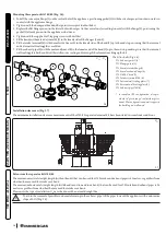
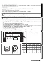
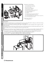
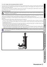
Страница 49: ... Gasvalve 6 Condensatedraintrap 7 D H W flowswitch 8 Manualairventvalve 9 Flowprobe 10 Air gasmixer 11 Systemexpansionvessel 12 Burner 13 Samplepoints airA fluegasesF 14 Flueprobe 15 Airintakepipe 16 Ignition detectionelectrode 17 Condensationmodule 18 Fan 19 Systempressureswitch 20 Returnprobe 21 Boilercirculatingpump 22 3barsafetyvalve 23 By pass 24 Systemdrainingcock ...

Страница 50: ...eheatingsystemifantifreezeisnotused b shut offallelectrical waterandgassupplies Inthecaseofworkormaintenancetostructureslocatedinthevicinityofductingordevicesforflueextractionandrelativeac cessories switch off the appliance and on completion of operations ensure that a qualified technician checks efficiency of the ductingorotherdevices Nevercleantheapplianceorconnectedpartswitheasilyflammablesubst...

Страница 51: ...gasmeterinterceptiondeviceorthemaininterceptiondevice ifpossible closethegasinterceptioncockontheproduct ifpossible opendoorsandwindowswideandcreateanaircurrent donotuseopenflames e g lighters matches donotsmoke donotuseelectricalswitches plugs doorbells telephonesorintercomdevicesinthebuild ing callanauthorisedcompany e g AuthorisedTechnicalAssistanceCentre ifyousmellburningorseesmokecomingoutoft...

Страница 52: ...n 13 BoilerinStand bymode 14 Presenceofexternalconnecteddevices 15 Flamepresencesymbol 16 Solarfunctionactive 17 Operationwithexternaltemperatureprobeactive optional 18 Boilermanometer 2 4 USINGTHEAPPLIANCE Boileractivation Beforeignitionmakesuretheheatingsystemisfilledwithwaterandthatthepressuregauge 18 indicatesapressureof1 1 2 bar Openthegascockupstreamfromtheboiler Iftheboileris off pressthe b...

Страница 53: ...R CM connectionerrorsymbolwillappearontheCARV2 TheCARV2 ishowev erpoweredconstantlysoasnottolosememorisedprograms Solarfunction Thisfunctionisautomaticallyactivatedifthe t3 ismorethan0seconds Duringawithdrawal aslongasthe Solarignitiondelay functionisactive theboilerdoesnotswitchon theD H W withdrawalsymbol flashesonthedisplayalongwiththeflashingsolarfunctionsymbol Whenthe Solarignitiondelay timeh...

Страница 54: ...ly on the domestic hot water NTC probe In this case only the antifreeze function is in hibited Inthiscasetheboilercontinuesto producedomestichotwaterbutnot withoptimalperformanceandwith possiblescaldingrisk 1 08 MaximumN ofresets Numberofallowedresetsalreadyperformed Theanomalycanbereset5consecu tivetimes afterwhichthefunctionis inhibitedforatleastonehouranditis possibletotryonceeveryhour fora max...

Страница 55: ...mode Inthis casethe CentralHeating 1 function cannotbeactivated 36 IMGBus communicationloss Communicationbetweenthevariouscomponentsisinter ruptedduetoananomalyontheboilercontrolunit onthe zonecontrolunitorontheIMGBus Theboilerdoesnotsatisfytheroom heatingrequests 1 37 Lowpowersupply voltage Thisoccurswhenthepowersupplyvoltageislowerthanthe allowedlimitsforthecorrectboileroperation Ifnormalconditi...

Страница 56: ...noma ly Theboilerdoesnotstart 1 60 Anomalypump blocked Thepumpisstoppedduetooneofthefollowingcauses Impellerblocked electricalfault Trytounblockthepumpasdescribed intherelativesection Ifnormal conditionsarerestoredtheboiler restartswithouthavingtobereset 1 61 Airincirculator Airisdetectedinsidethepump thepumpcannotwork Ventthepumpandthecentralheating circuit Ifnormalconditionsare restoredtheboiler...

Страница 57: ...1 2 90 Combustionsignal beyondlimit The combustion signal is beyond the adjustment range re quiredforanextendedperiodoftime Theboilerkeepsworking 1 2 91 Incorrectignition block Theboardhasexhaustedallpossibleactionsinordertoob tainoptimalignitionoftheburner PresstheResetbutton 1 92 Fanrevscorrection limit The system has exhausted all possible corrections of the numberoffanrevs Theboilerkeepsworkin...

Страница 58: ... Notused d0 8 Displaysthesystemreturnwatertemperature d0 9 Displaysthelistofthelastfiveanomalies Pressthe buttontodisplaytheanomalies Thenpressthe keystoscrollthelistofanomalies d1 0 Anomaly list reset Once d 1 0 is displayed press the Reset button deletion is confirmed via the 88 symbols flashing for two seconds d1 1 Notused d1 2 Displaysthepumpoperatingspeed d1 3 Notused d1 4 Displaysthepumpflow...

Страница 59: ...mptyingcock 5 Closeallpreviouslyopenedventvalves Iffluidcontainingglycolwasaddedtothesystemcircuit makesureitisrecoveredanddisposedofinaccordancewithstandard EN1717 2 10 EMPTYINGTHED H W CIRCUIT Todothis alwaysclosethedomesticcoldwaterinletupstreamoftheappliance Openanydomestichotwatertaptodischargethepressurefromthecircuit 2 11 ANTIFREEZEPROTECTION The appliance has an antifreeze function that sw...

Страница 60: ...ce technician Technical Data 2 14 PERMANENTSHUTDOWN In the event of permanent shutdown of the appliance contact professional staff for the procedures and ensure that the electrical water andgassupplylinesareshutoffanddisconnected ...

Страница 61: ...ageafterusingspraysandliquidstosearchforleaks LeakspraysandliquidsclogthereferenceholeP Ref Fig 41 ofthegasvalve damagingitirreparably Duringinstallationandmaintenance donotusesprayorliquidsintheupperareaofthegasvalve sidereferringtotheelectric connections Supplyofspareparts The device s warranty shall be rendered null and void if unapproved or unsuitable parts are used for maintenance or repairs ...

Страница 62: ...ensurecorrectignition checkthepropercalibrationofthenumberoffanrevolutions checktheCO2flowrateintheflue maximum intermediate minimum thevaluescomplywiththerelevanttables Par 3 3 checkactivationofthesafetydeviceintheeventofnogas aswellastherelativeactivationtime checkactivationofthemainswitchlocatedupstreamoftheboiler checkthattheintakeand orexhaustterminalsarenotblocked ensureactivationofalladjust...

Страница 63: ...sionvesselpressure isat1 0bar systemregulationprobesintervention Domestichotwatercontrolthermostatintervention Checksealingefficiencyofgascircuitandtheinternalsystem Checktheinterventionofthedeviceagainstnogasionisationflamecontrol Interventiontimemustbelessthan10seconds Checkthatthesystemstaticpressure withsystemcoldandafterrefillingthesystembymeansofthefillingvalve isbetween1and1 2 bar Checkvisu...

Страница 64: ...Fan 11 Ignition detectionelectrode 12 Flueprobe 13 Fluesamplepoint 14 Airsamplepoint 15 Fluehood 16 Burner 17 Air gasmanifold 18 Returnprobe 19 Systemexpansionvessel 20 Airventvalve 21 Boilercirculatingpump 22 Systempressureswitch 23 Systemfillingcock 24 Systemdrainingcock 25 3barsafetyvalve 26 Flowlimiter 27 D H W flowswitch G Gassupply AC Domestichotwateroutlet AF Domestichotwaterinlet SC Conden...

Страница 65: ...ostatjumper Y1 Gasvalve Colourcodekey Fig 40 BK Black BL Blue BR Brown G Green GY Grey OR Orange P Viola PK Pink R Red W White Y Yellow Y G Yellow Green ComandoAmicoRemotoV2 theboilerispreparedfortheapplicationoftheComandoAmicoRemotoremotecontrolV2 CARV2 which mustbeconnectedtoclamps41and44 40oftheterminalboard locatedintheboilercontrolpanel respectingthepolarityandelimi natingjumperX40 Roomthermo...

Страница 66: ...hepump Siphonblocked Dirtorcombustionproductsdepositedin side Checkthattherearenoresiduesofmaterialblockingtheflowof condensate Heatexchangerblocked Obstructionofthesiphon Checkthattherearenoresiduesofmaterialblockingtheflowof condensate Abnormalnoisesinthe system Airinthesystem Checktheopeningofthecapoftheairventvalve Par 1 32 Makesure thesystempressureandexpansionvesselpre chargevaluesarewithin ...

Страница 67: ...rdingthemodifiedgascontentontothedatanameplateintheconnectionbox Theseadjustmentsmustbemadewithreferencetothetypeofgasused followingtheindicationsgiveninthetable Par 4 2 Checksfollowingconversiontoanothertypeofgas Afterhavingmadesurethattheconversioniscompleteandthatthecalibrationhasbeensuccessful youmustmakesurethat thereisnoflameinthecombustionchamber theburnerflameisnottoohighorlowandthatitisst...

Страница 68: ...quests for central heating or DHW production and that the boiler is not in Stand by mode Intheeventofanomaly 62 or 72 Par 2 5 thedevicecancelsanyrequestsbyitself Duringthevariouscalibrationstages theCO2 valuecanbecheckedandpossiblycorrectedasdescribedin Par 3 10 Theenergyproducedisdissipatedviatheheatingcircuit alternatively theenergycanbereleasedfromtheDHWcircuitbyopeningany hotwatertap In this c...

Страница 69: ...brationfunctionhasfourphases Nominalheat output withthefunctionactive theboilercarriesouttheproceduresrequiredtocalibratetheapplianceatthenominalheatoutput Atthisstagethedisplayfeaturesflashingicons and andtheoperatingtemperaturealternatedwiththecurrentoperatingheat output 99 isdisplayed oncetheparametersaredetectedandstabilised the symbolwillstartflashing thismaytakeafewmin utes meaningthatthenom...

Страница 70: ...ssing the button Minimumheatoutput Afterhavingcalibratedtheboilerwiththeintermediateheatoutput itiscalibratedwiththeminimumheatoutput Atthisstagethedisplayfeaturesflashingicons and andtheoperatingtemperaturealternatedwiththecurrentoperatingheat output 0 isdisplayed oncetheparametersaredetectedandstabilised the symbolwillstartflashing meaningthattheminimal heatoutputsettingshavebeenset 47 Only afte...

Страница 71: ...low Duringcalibration whenthe symbolstartsflashing indicatingthecorrectacquisitionoftheparameters itispossibletoalterthe CO2 valuebypressingthebuttons5or6 Inthisphase thepreviouslyactivatediconstogetherwiththe externalconnecteddevicespresenceicon willflashonthedisplay andtheoperatingtemperaturealternatedwithcombustionsettingisdisplayed 48 Toincreasethecombustionsetting pressthebutton5 todecreaseit...

Страница 72: ...Stand by mode Intheeventofanomaly 72 Par 2 5 theboilercancelsanyrequestsbyitself Theenergyproducedisdissipatedviatheheatingcircuit alternatively theenergycanbereleasedfromtheDHWcircuitbyopeningany hotwatertap In this case the only active temperature control is the flow probe that limits the maximum temperature exiting the boiler at 90 C thereforebecarefulnottogetburned 49 Pressandholdbuttons and f...

Страница 73: ... At this stage the display features flashing icons and and the operating temperature is displayed alternated with the current operatingheatoutput Thecalibrationstages nominal intermediateandminimum progressautomaticallyandyoumustwaituntilcalibrationiscomplete ...

Страница 74: ...uttons and simultaneously until function activation which is displayed by indicating the fan operation speed in hundreds of revs and ignition of the flashing and sym bols Theapplianceremainsinthismodeforamaximumperiodof15minutes keepingthefanspeedconstant Thisfunctionendsonce15minuteshaveelapsed orbydisconnectingsupplyvoltagetotheboiler orbypressingthe button ChecktheΔPbetweenthetwopressuretestout...

Страница 75: ...rogramming phase press and hold the buttons and formorethan5seconds thedisplayshowstwodashes flashing 55 Nowenterthepassword 69 toaccesstheparametermenu To enter the first digit use the buttons to adjust the DHW to enter the seconddigit usethebuttonstoadjustthecentralheatingtemperature 56 Toconfirmthepassword 69 andaccessthemenu pressthe 57 Once in the menu you can cyclically scroll the submenus b...

Страница 76: ...ng its value press the button Exit the programming mode by waiting 15 minutes or by pressing the buttonuntilyoureturntothedesireddisplay Ifnecessarythedefaultvaluesrelatingtoparameters S and P0 P2 canbealteredbytemporarilymodifyingthetypeofgas parameter G and by restoring it according to the actual operating conditions wait for approximately 10 seconds between thegaschangeandthewhenitisrestored Th...

Страница 77: ...rnottocompromisethe properoperationoftheboiler 750 1700 rpm 1300 nG LG S1 Maxoutput S0 6900rpm 6200 nG LG S2 Ignitionoutput 2000 4500 rpm 3200 nG LG Intheeventofanalteration anomaly E62 appearsandcompletecalibrationisrequired Id Parameter Parameter Description Range Default Value value P0 DHWmax Definesthemaximumheatoutputpercentageoftheboiler duringtheD H W phasecomparedtothemaximumheat outputava...

Страница 78: ...couplingfunction 0 30seconds 0 t4 D H W priority timing Inwintermodetheboiler attheendofadomestichotwater request isreadytoswitchtocentralheatingmodeifthereis anactiverequest Timingsetsatimeperiodinwhichthe boilerwaitsbeforechangingtheoperatingmode inorderto quicklyandcomfortablysatisfyanadditionalrequestfor domestichotwater 0 100 seconds step 10sec 2 t5 Heating activation timing Theboilerhasanele...

Страница 79: ...ratureis increasedbyt10 0 15 0 t11 Notusedonthisboilermodel 0 1 0 Id Parameter Parameter Description Range Default Value value A0 Hydraulic model Definesthetypeofhydraulicsintheboiler 0 0 A1 Notusedonthisboilermodel A2 Circulating pumpmodel Definesthetypeofcirculatorintheboiler 0 1 0 A3 Maximum pumpspeed Setsthemaximumpumpoperatingspeed 1 9 9 A4 Minimum pumpspeed Setstheminimumpumpoperatingspeed 1...

Страница 80: ...ganyhotwater cockadjustingthepowerviathebuttons Themaximumpowerthancanbesupplied 99 isrelativetothepowersetbyparameter P2 Par 3 13 ThecentralheatingorD H W operatingmodeisdisplayedbytherelativesymbols or Afterthechecks deactivatethefunctionbyswitchingtheboileroffandstartingitagainusing Theboilerneedsacertainamountoftimetostabiliseitselfbeforecarryingoutacombustionparameterscheck Itisthusneces sary...

Страница 81: ...anelsforthethermalshockcharacteristicsanditscorrectexecution Tobeabletoactivatethefunctiontheremustbenoremotecontrolconnected whileincaseofsystemdividedintozonesitmust beproperlyconnected bothhydraulicallyandelectrically 61 The function is activated from boiler in off by pressing and holding the and buttonsformorethan5seconds Thefunctionlastsintotal7days 3daysatthelowertemperaturesetand4daysattheh...

Страница 82: ...rgrid Fig 62 Loosenthetwosidescrews a Loosenthetwoscrewsunderthefrontpanel b Removethegrid c Casingandcontrolpanel Fig 63 64 Removethecoveringcaps d Thenunscrewthetwofixingscrewsonthecontrolpanel e Pullthecasing f towardsyouandreleaseitfromitslowerseat Loosenthescrew g thatsecuresthecontrolpanel 1 a 1 3 3 a b 2 b 2 c 62 d 4 4 d 5 5 e e 63 7 g 6 6 f 64 ...

Страница 83: ...m h kg h 25 0 21500 D H W 99 2 72 99 2 00 24 0 20640 95 2 61 95 1 92 23 0 19780 91 2 50 91 1 84 22 0 18920 87 2 40 87 1 76 20 2 17372 HEAT D H W 79 2 20 79 1 62 20 0 17200 78 2 18 78 1 60 19 0 16340 74 2 07 74 1 52 18 0 15480 69 1 96 69 1 44 17 0 14620 65 1 86 65 1 36 16 0 13760 60 1 75 60 1 28 15 0 12900 56 1 64 56 1 20 14 0 12040 51 1 53 51 1 13 13 0 11180 46 1 43 46 1 05 12 0 10320 42 1 32 42 0...

Страница 84: ...onominalQ 9 2 0 2 10 2 0 2 CO2 toignitionQ 9 0 2 10 0 2 CO2 tominimumQ 9 0 2 10 0 2 COwith0 O2 atNom Min Q ppm 230 9 240 69 NOx with0 O2 atNom Min Q mg kWh 37 26 43 39 Fluetemperatureatnominaloutput C 65 65 Fluetemperatureatminimumoutput C 57 57 Maxaircombustiontemperature C 50 50 Combustionparameters measuringconditionsofusefulefficiency flowtemperature returntemperature 80 60 C ambienttemper atu...

Страница 85: ...output kW kcal h 25 21500 Domestichotwateradjustabletemperature C 20 60 Domestichotwatercircuitmin pressure dynamic bar MPa 0 3 0 03 Domestichotwatercircuitmax operatingpressure bar MPa 10 0 1 00 Flowratecapacityincontinuousduty T30 C l min 12 5 Weightoffullboiler kg 31 Weightofemptyboiler kg 29 Electricalconnection V Hz 230 50 Nominalpowerabsorption A 0 67 Installedelectricpower W 90 Pumpabsorbed...

Страница 86: ...NG Md Model Cod Md Modelcode SrN SerialNumber CHK Check Cod PIN PINcode Type Typeofinstallation ref CENTR1749 Qnwmin MinimumDHWheatinput Qnmin Centralheatingminimumheatinput Qnwmax DHWmaximumheatinput Qnmax Centralheatingmaximumheatinput Pnmin Minimumheatoutput Pnmax Maximumheatoutput PMS Maximumsystempressure PMW Maximumdomestichotwaterpressure D Specificflowrate TM Maximumoperatingtemperature NO...

Страница 87: ...4 87 3 At30 ofnominalheatoutputinalow temperaturemode P1 6 6 kW At30 ofnominalheatoutputinalow temperaturemode η1 95 8 Auxiliaryelectricityconsumption Otheritems Atfullload elmax 0 018 kW Heatlossinstandby Pstby 0 055 kW Atpartialload elmin 0 011 kW Ignitionburnerenergyconsumption Pign 0 000 kW Instandbymode PSB 0 004 kW Emissionsofnitrogenoxides NOx 32 mg kWh Formixedcentralheatingappliances Stat...

Страница 88: ...ter3ofthisbooklet forthemaintenancetechnician andadheretothefrequenciesandmethodsset outherein 2019 811 2013 A A B C D E F A A A A B C D kW dB 66 VICTRIXOMNIA 53 XL A A 20 Parameter value Annualenergyconsumptionforthecentralheatingmode QHE 38 5GJ Annualelectricityconsumptionforthedomestichotwaterfunction AEC 30kWh Annualfuelconsumptionforthedomestichotwaterfunction AFC 18GJ Seasonalspaceheatingene...

Страница 89: ... e g boiler solarthermalsystem Facsimileforfillinginthepackageficheforroomcentralheatingsystems Boiler and supplementary heat pump installed with low temperature heat emitters at 35 C FFrom the board of the heat pump Temperature control From temperature control board Supplementary boiler From boiler board Supplementary heat pump From the heat pump board Solar contribution and supplementary heat pu...

Страница 90: ...ution and supplementary heat pump Select the lowest value Boiler and supplementary heat pump installed with low temperature heat emitters at 35 C From the board of the heat pump in the distribution system and the size of the products compared to the size and features of the building Solar contribution From the board of the solar device Class I 1 Class II 2 Class III 1 5 Class IV 2 Class V 3 Class ...

Страница 91: ...ar contribution From the board of the solar device I 1 1 x I 10 x II III I Auxiliary electricity G F E D C B A A A A 27 27 27 28 27 27 27 28 30 30 30 32 33 34 35 36 36 37 38 40 39 50 55 60 65 75 80 85 100 115 123 131 130 150 160 170 163 188 200 213 M L XL XXL in the distribution system and the size of the products compared to the size and features of the building 1 2 3 3 2 3 2 69 ...

Страница 92: ...rproductionsystempackagefiche average climate conditions Colder 0 2 x Hotter 0 4 x Solar contribution From the board of the solar device _____ 1 1 x _____ 10 x _____ ____ ______ Auxiliary electricity G F E D C B A A A A 27 27 27 28 27 27 27 28 30 30 30 32 33 34 35 36 36 37 38 40 39 50 55 60 65 75 80 85 100 115 123 131 130 150 160 170 163 188 200 213 M L XL XXL in the distribution system and the si...

Страница 93: ...93 ...

Страница 94: ...94 ...

Страница 95: ...95 ...

Страница 96: ...bookletismade ofecologicalpaper immergas com ImmergasS p A 42041Brescello RE Italy Tel 0522 689011 Fax0522 680617 IMMERGASSPA ITALY CERTIFIEDCOMPANY UNIENISO9001 2015 Design manufactureandpost saleassistanceofgas boilers gaswaterheatersandrelatedaccessories ...

Отзывы: