background image

Part Number  550-142-302/0520


DO NOT USE BOILER DURING CONSTRUCTION

 unless you provide dust-free air to the boiler area or follow 

the requirements given on page 9. Failure to comply could result in severe personal injury, death or substantial property 
damage.

  This manual must only be used by a qualified heating installer/service technician. 

Before


installing

read all instructions, including this manual,  and any related supplements. Perform steps in the order 
given. Failure to comply could result in severe personal injury, death or substantial property damage. 

Now With Built In 

Low Water Cut Off Functionality

*

Blower cover on sizes CGi 25-6 only

*

Series 4


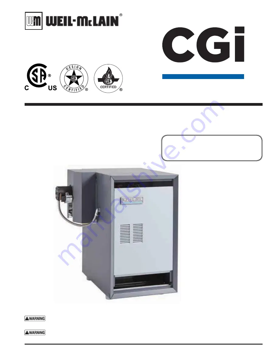
Gas-Fired Water Boilers

Boiler Manual

• Maintenance

• Parts

• Installation

• Startup

Содержание CGi 4 Series

Страница 1: ...anual must only be used by a qualified heating installer service technician Before installing read all instructions including this manual and any related supplements Perform steps in the order given Failure to comply could result in severe personal injury death or substantial property damage Now With Built In Low Water Cut Off Functionality Blower cover on sizes CGi 25 6 only Series 4 Gas Fired Wa...

Страница 2: ...age 49 Transformer The control transformer reduces line voltage to 24 volts for the gas valve and limit circuit Inducer The inducer pulls flue gases through the boiler causing air to be pulled in through the boiler air openings The inducer pushes the flue gases through the vent pipe as well Air pressure switch The air pressure switch signals the control module telling the control module whether the ...

Страница 3: ...Part Number 550 142 302 0520 CGi SERIES 4 GAS FIRED WATER BOILER Boiler Manual 3 CGi Series 4 Gas Fired Induced Draft Water Boiler ...

Страница 4: ... Handling ceramic fiber and fiberglass materials 69 Hazard definitions The following defined terms are used throughout this manual to bring attention to the presence of hazards of various risk levels or to important information concerning the life of the product Indicates presence of hazards that will cause severe personal injury death or substantial property damage Indicates presence of hazards that ...

Страница 5: ...longer be covered under warranty and should be replaced Electrical Damage If any electrical component or wir ing came into contact with water or was suspected to have come into contact with water replace the boiler with a new Weil McLain boiler Frozen Water Damage Hazard Residences or buildings that are unattended in severely cold weather boiler system components failures power outages or other el...

Страница 6: ...in ANSI Z21 13 latest edition For the Commonwealth of Massachusetts read and follow the special instructions located on page 15 of this manual Before locating the boiler check the following Check for nearby connection to System water piping Venting connections Gas supply piping Electrical power Check area around boiler Remove any combustible materials gasoline and other flammable liquids or other c...

Страница 7: ...mum dimensions are 25 inch length by Minimum foundation width CGi 25 3 12 CGi 6 21 CGi 4 15 CGi 7 24 CGi 5 18 CGi 8 27 Recommended SERVICE clearances Fig 1a 1 Provide clearances for cleaning and servicing the boiler and for access to controls and components See Figure 1a for recommen dations 2 Provide at least screwdriver clearance to jacket front panel screws for removal of front panel for inspec...

Страница 8: ...ng the appropriate tables in Part 13 of that code Canadian installations must comply with B149 1 or B149 2 Natural Gas and Propane Installation Code Chimney or vent requirements 1 Venting must be installed according to Part 7 Venting of Equipment of National Fuel Gas Code ANSI Z223 1 NFPA 54 latest edition and applicable building codes Canadian installations must comply with B149 1 or B149 2 Natur...

Страница 9: ...or products or areas listed below before installing boiler If any of these contaminants are found remove contaminants permanently OR isolate boiler and provide outside combustion air See national provincial or local codes for further information Products to avoid Areas likely to have contaminants Spray cans containing chloro fluorocarbons Dry cleaning laundry areas and establishments Permanent wave...

Страница 10: ...provide two openings within 12 inches of the ceiling and the floor sized per Figure 3 3 See Figure 4 Air supplied through vertical ducts provide two openings terminated within 12 inches of the ceiling and the floor sized per Figure 4 4 See Figure 5 Air supplied through horizontal ducts provide two openings within 12 inches of the floor and the ceiling sized per Figure 5 Air openings must be provided ...

Страница 11: ... on page 10 provided Clearances from boiler to walls The boiler must have clearances of at least those shown in Figure 1a page 7 Opening must be directly to outside The opening must connect directly to the outdoors or to a space that communicates directly to the outdoors not to an interior space Theaircanbeprovidedthroughadirectopeningorthroughahorizontal or vertical duct Opening placement The top...

Страница 12: ...te boiler without burner shield in place Failure to do so could result in severe personal injury death or sub stantial property damage Orifice replacement procedure when required 1 Remove the screws securing the burner shield and remove burner shield 2 Using a 7 16 open end wrench remove the burner orifices from the manifold 3 Apply a small amount of pipe dope to each of the new orifices and install ...

Страница 13: ...ed air during the fill Valve and nipple are not included with boiler Fill and pressure test 1 Open the shutoff valves you installed on supply and return connections 2 Slowly open boiler drain valve and fresh water sup ply to fill boiler with water 3 When water flows from shutoff valves close boiler drain valve 4 Close shutoff valves 5 Slowly reopen boiler drain valve until test pressure on the pressu...

Страница 14: ...Natural Gas and Propane Installation Code 2 To prevent downdrafts chimney should extend at least 3 feet above the highest point where it passes through a roof and at least 2 feet higher than any portion of a building within a horizontal distance of 10 feet 3 To vent with another appliance see National Fuel Gas Code ANSI Z223 1 NFPA 54 latest edition or in Canada B149 2 or B149 2 Natural Gas and Pr...

Страница 15: ...be installed 2 APPROVED CARBON MONOXIDE DETECTORS Each carbon monoxide detector as required in accordance with the above provisions shall comply with NFPA 720 and be ANSI UL 2034 listed and IAS certified 3 SIGNAGE A metal or plastic identification plate shall be perma nently mounted to the exterior of the building at a minimum height of eight 8 feet above grade directly in line with the ex haust ven...

Страница 16: ...ue gas spillage resulting in severe personal injury or death 3 Follow all applicable national state local or provin cial codes when venting the CGi boiler 4 Connect vent starter to blower housing outlet as shown in the Figures 8 through 11 a Do not mix components from different vent manufacturers b Maintain minimum 2 clearance from com bustible materials to vent pipe c Seal with sealant specified b...

Страница 17: ...tional Fuel Gas Code ANSI Z223 1 NFPA 54 latest edition and or the Natural Gas and Propane Installation Code CAN CSA B149 1 The vent termination clearances below are for U S A for Canadian vent termination clearances please refer to the requirements of CSA B149 1 Natural Gas and Propane Installation Code Consideration should be given to avoid possible damage caused by vent plumes and condensate wh...

Страница 18: ...CGi 8 Elbow and termination coupling with screen not available for StaR 34 6 Do not seal vent pipe slip connector for Saf TVent to inside or outside plate 7 If passing through noncombustible wall provide hole diameter large enough to insert the vent pipe slip connector for Saf T Vent 8 Install horizontal drain tee as close as possible to boiler in first horizontal run See Figures 13 and 14 9 Do not...

Страница 19: ...IRED WATER BOILER Boiler Manual 19 Venting direct exhaust installation cont 3f Figure 15 Sidewall termination Using any termination other than one of those shown could cause nuisance outages and loss of heat resulting in substantial property damage ...

Страница 20: ...ystems large volume systems originally designed for circulation by natural convection rather than a pump See page 29 for boilers used with refrigeration systems Chillers or air handling units Install boiler such that Chilled medium if used is piped in parallel with heating boiler Use appropriate valves to prevent chilled medium from entering boiler ConsultAHRI Installation and Piping Guides If boi...

Страница 21: ...izes Closed type expansion tank Figure 17 1 Ensure expansion tank size will handle boiler and system water volume and temperature See tank manufacturer s instructions for details 2 Connect tank to NPT tapping located behind supply outlet using NPT piping Pitch any horizontal piping up towards tank 1 inch per 5 feet of piping Use Figure 16 or Figure 17 only for single zone systems designed for retu...

Страница 22: ... flow rate without affecting primary circuit flow rate If Figures 20 or 21 cannot be used use the boiler by pass piping shown in Figure 22 or Figure 23 on page 27 You can also use the piping shown in Figure 24 on page 29 system bypass if the reduced flow rate in the heating system will not cause heat distribution problems Failure to prevent low return water temperature to the boiler could cause corro...

Страница 23: ...ystem causing waterlogging of the expansion tank 11 Fill valve 12 Diaphragm type or bladder type expansion tank if used For closed type expansion tank pipe from top of air separator to tank fitting as in Figure 17 13 Air separator and automatic vent if used Note that the fill valve must always be connected to the expansion tank regardless of loca tion of expansion tank circulator or air separator Fo...

Страница 24: ...ill not cause a change in the heating circuit rate and temperature distribution Figures 20 and 21 show suggested bypass arrangements using primary secondary bypass piping preferred for low temperature systems such as radiant heating systems or converted gravity systems For alterna tives see pages 26 through 29 The bypass valves items 7a and 7b provide mixing of hot boiler outlet water with cooler ...

Страница 25: ...to tank fitting closed type expansion tank DO NOT usean automaticairvent when usingclosed typeexpansiontank It would allow air to leave the system causing waterlogging of the expansion tank 11 Fill valve 12 Diaphragm type or bladder type expansion tank if used For closed type expansion tank pipe from top of air separator to tank fitting as in Figure 17 13 Air separator and automatic vent if used Not...

Страница 26: ...ed to the radiant tubing Gauge 8 is required on all systems to assure reliable adjustment of the bypass valves The boiler mounted temperature pressure gauge can be used if a separate temperature gauge is not installed Valve adjustment 1 Start with valve 7a fully closed and 7b fully open 2 Gradually open valve 7a while closing valve 7b until the temperature at gauge 8 reads 60 F higher than gauge 4...

Страница 27: ...atic air vent when using closed type expansion tank It would allow air to leave the system causing waterlogging of the expansion tank 11 Fill valve 12 Diaphragm type or bladder type expansion tank if used For closed type expansion tank pipe from top of air separator to tank fitting as in Figure 17 page 21 13 Air separator and automatic vent if used Note that the fill valve must always be connected t...

Страница 28: ...the beginning of the system and reduced heat from radiators near the end of the system Valve adjustment 1 Start with valve 7a fully closed and 7b fully open 2 Gradually open valve 7a while closing valve 7b until the temperature at gauge 8 reads at least 130 F at all times 3 Valve 7a regulates the amount of boiler supply water mixed with return water Valve 7b causes a pressure drop in the system ne...

Страница 29: ...type expansion tank pipe from top of air separator to tank fitting as in Figure 17 page 21 Figure 24 System bypass piping Zoning with zone valve or circulators return water 130 F or higher Alternative to boiler bypass piping Figures 22 and 23 Figure 25 Piping refrigeration systems 4e Water piping refrigeration system Prevent chilled water from entering boiler Install boiler so that chilled medium i...

Страница 30: ...g to be extended to the floor use appropriate length of pipe between cap and tee b Install ground joint union for servicing when re quired c Install manual shutoff valve in gas supply piping out side boiler jacket when required by local codes or utility requirements d In Canada When using manual main shutoff valve it must be identified by the installer 2 Support piping with hangers not by boiler or ...

Страница 31: ...con nected to it If connected directly to boiler set for 0 1 amps plus gas valve current See information on wiring diagram as shown in Figure 32 page 39 For other devices refer to manufacturer s specifications Wiring diagram on boiler gives setting for control module and gas valve Also see instructions with thermostat DHW Connect DHW aquastat as shown in wiring below Economy function isn t utilized...

Страница 32: ...roleum based cleaning or sealing compounds in boiler system Severe damage to boiler will occur resulting in substantial property damage Eliminate all system leaks Continual fresh makeup water will reduce boiler life Minerals can build up in sections reducing heat transfer overheating cast iron and causing section failure Verify water chemistry Consult local water treatment companies for unusually ...

Страница 33: ...ghout the system i If purge valves are not installed in system open manual air vents in system one at a time beginning with lowest floor Close vent when water squirts out Repeat with remaining vents 4 Open automatic air vent diaphragm type or bladder type expansion tank systems only one turn 5 Open other vents a Starting on the lowest floor open air vents one at a time until water squirts out b Repe...

Страница 34: ...ure setting and counterclockwise to decrease When the knob is turned to adjust temperature the display will brighten to indicate adjustment mode After temperature is set to desired value display will dim after approximately 5 seconds to indicate measurement mode ADJUST BOILER OPERATING TEMPERATURE TO DESIRED SETPOINT BOILER ECONOMY SETTING To comply with Department of Energy regulations the contro...

Страница 35: ... 7b Check burner flames View pilot and main flames through the inspection port in the base burner shield Pilot burner flame Figure 28 PROPER pilot flame characteristics 1 Blue flame 2 Inner cone engulfing pilot flame sensor 3 Pilot flame sensor glowing cherry red IMPROPER pilot flame characteristics 1 Overfired Large flame lifting or blowing past pilot flame sensor 2 Underfired Small flame Inner cone not engulfi...

Страница 36: ...n shutoff gas valve Manometer should confirm there is no gas flow e Pilot will relight flame sensing element will sense pilot flame and main burners will reignite Set limit control s to system temperature requirements Adjust balancing valves and controls to provide design temperature to system Set Economy mode For multiple zones adjust flow so it is about the same in each zone Verify thermostat heat an...

Страница 37: ...1 when power is restored 6 In the event the limit control shuts down the boiler The control module closes the pilot and main gas valves but keeps the inducer operating for 15 second postpurge This boiler is equipped with a control system that automatically adjusts a time delay period to turn on the boiler during a call for heat This is accomplished by circulating available hot water in the system ...

Страница 38: ...0 Figure 30 STEPS Call for Heat POWER TSTAT CIRC LIMIT PURGE FLAME LWCO Timing 1 Standby Waiting for call for heat NO 2 Call for heat Circulator on YES 3 Limit circuit Limit controls closed Rollout TFE contacts closed YES 4 Inducer Inducer turns on YES 5 Pressure circuit Pressure switch contacts closed Prepurge for 10 seconds YES 35 sec 6 Flame proven Gas valve open Ignitor remains on Boiler produ...

Страница 39: ...Part Number 550 142 302 0520 CGi SERIES 4 GAS FIRED WATER BOILER Boiler Manual 39 Operation wiring diagrams 9b Figure 31 Schematic wiring diagram ...

Страница 40: ...Part Number 550 142 302 0520 CGi SERIES 4 GAS FIRED WATER BOILER Boiler Manual 40 Operation wiring diagrams continued 9b Figure 32 Ladder wiring diagram ...

Страница 41: ...Part Number 550 142 302 0520 CGi SERIES 4 GAS FIRED WATER BOILER Boiler Manual 41 9c Operating instructions CGi 25 thru 6 Spark pilot Natural or propane gas Gas valve Honeywell VR8204 VR8304 ...

Страница 42: ...Part Number 550 142 302 0520 CGi SERIES 4 GAS FIRED WATER BOILER Boiler Manual 42 9c Operating instructions CGi 25 thru 6 Spark pilot Natural or propane gas Gas valve White Rodgers 36E ...

Страница 43: ...Part Number 550 142 302 0520 CGi SERIES 4 GAS FIRED WATER BOILER Boiler Manual 43 9c Operating instructions CGi 25 thru 8 Spark pilot Natural or propane gas Gas valve White Rodgers 36C ...

Страница 44: ...Inspect Reported problems Boiler area Air openings Flue gas vent system and air piping Pilot and main burner flames Water piping Boiler heating surfaces Burners base and inlet air box Condensate drain system Service Inducer motor Temperature LWCO sensor Start up Perform start up per manual Check test Gas piping Cold fill and operating pressures Air vents and air elimination Limit controls and cutoff...

Страница 45: ... leaks from the boiler If found locate source of leaks and repair Inspect Reported problems Inspect any problems reported by owner and correct before proceeding Boiler area 1 Verify that boiler area is free of any combustible materials gasoline and other flammable vapors and liquids 2 Verify that boiler area and air intake is free of any of the contaminants listed in Table 1 on page 9 of this manua...

Страница 46: ...clear run a vacuum at the burner inlet while cleaning the burner ports with a wire brush The vacuum will help to draw any airborne material out of the burner 4 Reinstall components starting with the burner tray then the pilot bracket assembly burner baffle and air inlet top and front panels 5 Follow the start up procedure in the boiler manual Condensate drain system 1 Inspect condensate drain fittin...

Страница 47: ...s Open type located above highest radiator or baseboard unit usually in the attic or closet Has a gauge glass and overflow pipe to a drain Closed type welded gas tight and located above boiler Tank is partially filled with water leaving an air cushion for expansion Make sure this type of tank is fitted with a tank fitting such as the B G Tank Trol or Taco Taco Trol This fitting reduces gravity circulat...

Страница 48: ...found check for proper combustion and make any necessary adjustments Safety relief valves should be reinspected AT LEAST ONCE EVERY THREE YEARS by a licensed plumbing contractor or authorized inspection agency to ensure that the product has not been affected by corrosive water conditions and to ensure that the valve and discharge line have not been altered or tampered with illegally Certain natura...

Страница 49: ... for mo mentary testing as outlined in Troubleshooting Charts Severe personal injury death or substantial property dam age can result Before troubleshooting 1 Have the following items a Voltmeter that can check 120VAC and 24VAC b Microammeter with a minimum scale range of 0 25 c Continuity checker d U tube manometer 2 Check for 120VAC minimum 102VAC to maximum 132VAC to boiler 3 Make sure thermost...

Страница 50: ...er to read resistance value between thermistor and thermistor common See Figure 38 page 52 for sensor plug details Table 10 Temperature LWCO sensor resistance values Troubleshooting air pressure reading 1 If manometer reading is lower than the setpoint of the switch see Table 9 check for possible causes blockage in hoses obstruction in inducer housing outlet loose inducer wheel on motor shaft indu...

Страница 51: ...lems based on indicator light condi tions Control indicator lights LOCKOUT modes See Charts 1 through 8 in this section for detailed troubleshoot ing procedures Control indicator lights HARD LOCKOUT Summary Flashing LED s MAY remove 120VAC power for more than 2 seconds to clear lockout OR ignition control will automatically restart sequence of operation after 1 hour waiting period after fault cond...

Страница 52: ...5 0 7 385 2 0 9 9 1 9 WR FLUFXODWRU KLWH HOORZ 7KHUPRVWDW 9 1 9 ODFN 9 1 KLWH QWUDQFH JURXQG UHHQ ODFN ODFN UHHQ WR URXQG OXH WR LI XVHG 767 7 OXH WR LI XVHG ODFN WR 7UDQVIRUPHU RPPRQ 5HG WR 7UDQVIRUPHU RW 5HG ZLUH WR JDV YDOYH 09 OXH ZLUH WR JDV YDOYH 39 URZQ KLWH ZLUH WR JDV YDOYH 09 39 9 FRQWURO FLUFXLWV WR 6SLOO 6ZLWFK DQG WR GGLWLRQDO OLPLWV LI XVHG HOORZ ODPH VHQVH ZLUH WR SLORW 9 WR LQGXFHU...

Страница 53: ...lug Figure 38 Item 3 page 52 on control module Using voltmeter check across black and white wire pins of 120 VAC IN plug Does voltmeter indicate 120 VAC No Yes Reconnect 120 VAC IN plug Remove transformer plug Figure 38 Item 2 page 52 on control module Using voltmeter check across left side top and bottom pins of transformer receptacle Does voltmeter indicate 120 VAC No Yes Reinstall 120 VAC trans...

Страница 54: ...xternal circuit one at a time and check the voltmeter reading across the wires There should NEVER be a voltage reading If a voltage does occur under any condition check and correct the external wiring This is a common problem when using 3 wire zone valves Once the external thermostat circuit wiring is checked and corrected if necessary reconnect the external thermostat circuit wires to the boiler ...

Страница 55: ...ry Retest Clear passages and recycle boiler Recheck boiler operation Try reseating plug in module receptacle and restart If inducer still does not work replace inducer assembly Retest Boiler should be in normal operating sequence Observe operation until thermostat is satisfied and inducer has completed its post purge cycle Remove INDUCER plug Figure 38 Item 6 page 52 from plug receptacle of control...

Страница 56: ...r Are FLAME POWER No Yes Replace control module Retest Boiler should now operate normally Original flashing FLAME light caused by gas valve not operating properly See normal sequence of operation Figure 30 page 38 Turn off power to the boiler at service switch or breaker Wait at least 45 seconds Turn on power to boiler Restart boiler following Operating instructions in this manual Section 9c Look t...

Страница 57: ...sure switch Reseat connector in control module receptacle If harness is intact and properly seated but problem persists replace control module Retest Check air pressure switch per manual Section 11b Replace if necessary Retest Clear vent and recycle boiler Recheck boiler operation Replace inducer assembly Retest Boiler should be in normal operating sequence Observe operation until thermostat is sa...

Страница 58: ...e in good condition Spark gap should be approximately 1 8 Correct any above problems replacing pilot if burner or wiring is damaged Reinstall burner shield to operate boiler for retest after any changes or corrections If none of the above corrects problems then replace the control module and retest to boiler at service switch or breaker Remove burner shield see Figure 40 item 4 page 64 for locatio...

Страница 59: ...losing water Repair leak and retest Is boiler pressurized Yes No System was low on water Check system fill piping for leaks or damage Pressurize boiler to system design pressure Are lights still solid No Yes Check system for leaks Is system leaking or not maintaining pressure No Yes LWCO sensor is bad or fouled Clean LWCO sensor Retest Are lights still solid No Yes Sensor is bad Replace sensor Rete...

Страница 60: ... damage Check temperature sensor for correct resistance Are resistance values correct No Yes Replace control module Retest Replace control module Retest Repair replace circulator Retest Repair replace wiring Retest Check any other limit controls wired into the limit circuit If all are OK then replace control module Retest Correct conditions and recheck operation See Figure 30 page 38 for normal se...

Страница 61: ...Part Number 550 142 302 0520 CGi SERIES 4 GAS FIRED WATER BOILER Boiler Manual 61 Notes ...

Страница 62: ...size and include description and part number of replacement part Results from using modified or other manufactured parts will not be covered by warranty and may damage boiler or impair operation Weil McLain part numbers are found in Weil McLain Boilers and Controls Repair Parts Lists The boiler contains ceramic fiber and fiberglass materials Use care when handling these materials per instructions on ...

Страница 63: ... includes seals and sealant for 1 joint 381 354 527 4 Tie rod without nut 3 per boiler CGi 25 and CGi 3 CGi 4 CGi 5 CGi 6 CGi 7 CGi 8 560 234 500 560 234 501 560 234 502 560 234 503 560 234 504 560 234 505 5 Nut 2 per tie rod 561 928 235 Item Description Weil McLain part number 6 Washer 1 per tie rod 562 248 684 7 E CGi 4 8 460 003 017 8 Collector hood and transition assembly CGi 25 CGi 3 CGi 4 CG...

Страница 64: ... 003 691 450 003 692 450 003 693 450 003 795 450 003 796 8b Rear spacing strip CGi 25 CGi 3 CGi 4 CGi 5 CGi 6 CGi 7 CGi 8 550 320 160 550 320 161 550 320 162 550 320 163 550 320 164 550 320 165 8c Nut hex 5mm Zp 550 320 170 9 Base insulation kit CGi 25 CGi 3 CGi 4 CGi 5 CGi 6 CGi 7 CGi 8 381 354 330 381 354 331 381 354 332 381 354 333 381 354 334 381 354 335 10 Boiler leg kit 550 320 219 11 Manifo...

Страница 65: ...Part Number 550 142 302 0520 CGi SERIES 4 GAS FIRED WATER BOILER Boiler Manual 65 Replacement parts base continued 12c ...

Страница 66: ...381 359 231 381 359 232 381 359 233 381 359 234 381 359 235 381 359 242 381 359 242 381 359 243 381 359 244 381 359 245 381 359 246 381 359 247 CGi 25 CGi 3 CGi 4 CGi 5 CGi 6 CGi 7 CGi 8 Boiler Model 6 7 8 9 10 11 Boiler Model S bottom front S interior S rear V touch up paint _ Weil McLain part number CGi 25 CGi 3 CGi 4 CGi 5 CGi 6 CGi 7 CGi 8 381 359 254 381 359 254 381 359 255 381 359 256 381 35...

Страница 67: ...ation pressure temperature gauge 3 diameter short shank 380 000 000 3 Drain valve 511 210 423 511 246 392 511 246 392 511 246 392 4 Circulator CGi 25 through CGi 5 CGi 6 through CGi 8 511 405 153 511 405 113 5 Circulator gasket universal 2 per boiler 590 317 535 not shown Circulator hardware kit includes 1 flange 2 nuts 2 screws 1 gasket NPT CGi 25 1 NPT CGi 3 through CGi 5 1 NPT CGi 6 and CGi 7 NP...

Страница 68: ... w orifice aluminum pilot gas tubing 511 330 081 Natural gas and propane gas components 3 Control module 381 330 040 not shown Wiring harness Controls to control module 591 391 978 4 Air pressure switch CGi 25 CGi 3 CGi 4 CGi 5 CGi 6 CGi 7 CGi 8 381 359 280 381 359 280 381 359 281 381 359 282 381 359 283 381 359 284 381 359 285 5 Control transformer 381 356 578 not shown Tubing air pressure switch ...

Страница 69: ... model number Supply tapping inches NPT Return tapping inches NPT Gas connection size Note 3 inches NPT Gas manifold size Note 3 inches NPT W Jacket width inches CGi 25 1 1 10 CGi 3 1 1 10 CGi 4 1 1 13 CGi 5 1 1 16 CGi 6 1 1 19 CGi 7 1 1 22 CGi 8 1 1 25 Note 3 Gas piping from meter to boiler to be sized per local utility requirements ...

Страница 70: ...boiler 2 Based on standard test procedures prescribed by the United States Department of Energy 3 Net AHRI ratings are based on net installed radiation of sufficient quantity for the requirements of the building and nothing need be added for normal piping and pickup Ratings are based on a piping and pickup allowance of 1 15 An additional allowance should be made for unusual piping and pickup loads ...

Страница 71: ...stion chamber lining or base insulation from the boiler and place it in a plastic bag for disposal Wash potentially contaminated clothes separately from other clothing Rinse clothes washer thoroughly NIOSH stated First Aid Eye Irrigate immediately Breathing Fresh air REMOVAL OF FIBERGLASS WOOL or INSTALLATION OF FIBERGLASS WOOL COMBUSTION CHAMBER LINING OR BASE PANELS Thisproductcontains fiberglass...

Страница 72: ...Part Number 550 142 302 0520 72 CGi SERIES 4 GAS FIRED WATER BOILER Boiler Manual ...

Отзывы: