


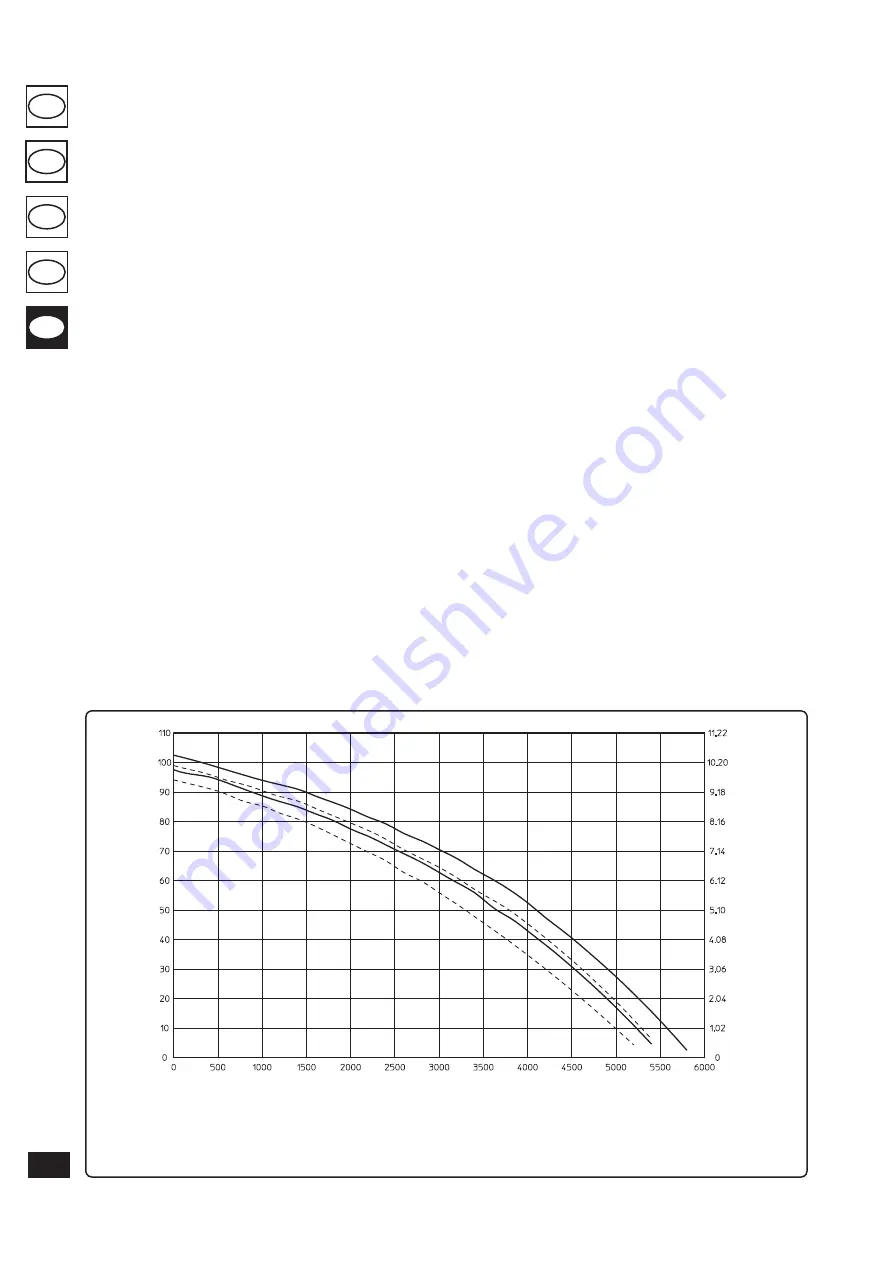
Total head available to the system.
Fig. 1-24
1.16 GAS SYSTEM START-UP.
To start up the system proceed as follows:
- open windows and doors;
- avoid presence of sparks or naked flames;
- bleed all air from pipelines;
- check that the internal system is properly sealed
according to specifications.
1.17 BOILER START-UP (IGNITION).
For issue of the Declaration of Conformity pro-
vided for by Italian Law, the following must be
performed for boiler start-up:
- check that the internal system is properly sealed
according to specifications;
- make sure that the type of gas used corresponds
to boiler settings;
- switch the boiler on and check correct igni-
tion;
- check that the n° of fans revs is that indicated
in the book (Par. 3-21);
- ensure that the safety device is engaged in the
event of gas supply failure and check activation
time;
- check activation of the main switch located
upstream from the boiler and in the boiler;
- check that the intake/exhaust concentric ter-
minal (if fitted) is not blocked.
The boiler must not be started up even if only
one of the checks should be negative.
N.B.:
the boiler preliminary check must be carried
out by a qualified technician. The boiler warranty
is valid as of the date of testing.
The test certificate and warranty is issued to the
user.
1.18 CIRCULATION PUMP.
The “Victrix 115 1 I” series boilers are supplied
with a built-in circulation pump with 3-posi-
tion electric speed control. The boiler does not
operate correctly with the circulation pump on
first speed. To ensure optimal boiler operation,
in the case of new systems (single pipe and
module) it is recommended to use the pump
at maximum speed. The pump is already fitted
with a condenser.
Pump release.
If, after a prolonged period of
inactivity, the circulation pump is blocked,
unscrew the front cap and turn the motor shaft
using a screwdriver. Take great care during this
operation to avoid damage to the motor.
1.19 KITS AVAILABLE ON REQUEST.
• Cascade and zones heat adjuster kit.
• Support kit for fixing the heat adjuster to the
wall.
• Zone manager kit.
• Modulating room thermostat kit.
• External probe kit.
• System flow probe kit.
• DHW probe kit for external storage tank.
• Anti-freeze with -15 °C resistance kit.
• Individual boiler safety devices stub pipes kit.
• Boilers in cascade safety devices stub pipes
kit.
• Three-way valve kit for coupling external sto-
rage tank unit.
• Individual boiler hydraulic manifold kit.
• Hydraulic connection manifolds kit with two
boilers in cascade.
• Additional boiler in cascade hydraulic manifold
kit.
• Flue exhaust manifold kit with flue adjusting
devices with two boilers in cascade.
• Flue exhaust manifold kit with flue adjusting
device with additional boiler in cascade.
• Ø80/125 horizontal concentric kit.
• Ø80/125 vertical concentric kit.
• Ø 80 horizontal kit with flue exhaust.
• Ø 80 horizontal terminal kit with wall flue
exhaust.
• Ø80 vertical terminal kit.
The above-mentioned kits are supplied complete
with instructions for assembly and use.
A = Head available to the system on the individual boiler maximum speed.
B = Head available to the system on the individual boiler second speed.
C = Head available to the system on maximum speed with the non-return valve for boilers in cascade (battery)
D = Head available to the system on second speed with the non-return valve for boilers in cascade (battery)
H
ea
d (m H
2
O)
Flow rate (l/h)
H
ea
d (kP
a)
A
B
C
D
124
TR
SI
RU
IE
CZ
Содержание VICTRIX 115 1 I
Страница 2: ......
Страница 145: ......
Страница 146: ...www immergas com This instruction booklet is made of ecological paper Cod 1 029592 Rev 15 031093 001 01 10 ...


