


Fuel gas quality.
The appliance has been designed
to operate with gas free of impurities; otherwise it
is advisable to fit special filters upstream from the
appliance to restore the purity of the gas.
Storage tanks (in case of supply from LPG
depot).
- New LPG storage tanks may contain residual
inert gases (nitrogen) that degrade the mixture
delivered to the appliance casing functioning
anomalies.
- Due to the composition of the LPG mixture,
layering of the mixture components may occur
during the period of storage in the tanks. This
can cause a variation in the heating power of
the mixture delivered to the appliance, with
subsequent change in its performance.
Hydraulic connection.
Important:
In order not to void the warranty
before making the boiler connections, carefully
clean the heating system (pipes, radiators, etc.)
with special pickling or de-scaling products to
remove any deposits that could compromise
correct boiler operation.
It is recommended to prepare a filter in the
system to collect and separate any impurities
present in the system (slurry remover filter).
In order to avoid scaling in the central heating
system, the provisions given in the regulations on
water treatment in heating systems for civil use
must be respected. Water connections must be
made in a rational way using the couplings on the
boiler template. The discharge of the boiler safety
valve must be connected to a discharge funnel
that is present in the boiler but not installed
and then connected to a sewer. Otherwise, the
manufacturer declines any responsibility in case
of flooding if the drain valve cuts in.
Condensate drain.
To drain the condensate pro-
duced by the appliance, it is necessary to connect
to the drainage system by means of acid conden-
sate resistant pipes having an internal diameter
of at least 13 mm. The system connecting the
appliance to the drainage system must be carried
out in such a way as to prevent freezing of the
liquid contained in it. Before appliance start-
up, ensure that the condensate can be correctly
removed. Also, comply with national and local
regulations on discharging waste waters.
Electrical connection:
The electric plant must be
realised in compliance with the law. The “Victrix
115 1 I” boiler has an IPX5D protection rating for
the entire appliance. Electrical safety of the unit
is reached when it is correctly connected to an
efficient earthing system as specified by current
safety standards.
Important:
Immergas S.p.a. declines any respon-
sibility for damage or physical injury caused by
failure to connect the boiler to an efficient earth
system or failure to comply with the reference
standards.
Also ensure that the electrical installation cor-
responds to maximum absorbed power speci-
fications as shown on the boiler data-plate. The
boilers are supplied complete with an “X” type
power cable without plug. The power supply cable
must be connected to a 230V ±10% / 50Hz net-
work respecting the L-N polarity and the earth
connection
, An omnipolar disconnection
must be envisioned on this network with a class
III overvoltage category. The main switch must
be installed outside the rooms in a position that
is indicated and accessible. When replacing the
power supply cable, contact a qualified techni-
cian (e.g. the Immergas After-Sales Technical
Assistance Service). The power cable must be
laid as shown.
In the event of mains fuse replacement on the
connection terminal board, use a 2A quick-
blow fuse. For the main power supply to the
appliance, never use adapters, multiple sockets
or extension leads.
If during connection the L-N polarities are not
respected, the boiler does not detect flame pre-
sence and goes into ignition block.
Important:
also in the case in which the L-N
polarity is not respected, if there is temporary
residual voltage exceeding 30V on the neutral,
the boiler could function all the same (but only
temporarily). Measure the voltage using appro-
priate instruments, without trusting the voltage
tester screwdriver.
1.8 COMMANDS FOR HEAT
ADJUSTMENT (OPTIONAL).
The boiler is prepared for the application of a
cascade and zone regulator, zone manager and
external probe.
These components are available as separate kits
to the boiler and are supplied on request.
Carefully read the user and assembly instructions
contained in the accessory kit.
• The cascade and zone regulator (Fig. 1-6) is
connected to the boiler using only two wires,
powered at 230 V and allows to:
- manage a hydraulic circuit with 2 mixed
zones (mixing valve); 1 direct zone; 1 Storage
tank unit and relative pumps;
- self-diagnosis system to display any boiler
functioning anomalies;
- to set two room temperature values: one for
day (comfort temperature) and one for night
(lower temperature);
- to manage the temperature of the DHW (with
a storage tank unit);
- to manage the boiler flow temperature de-
pending on the external temperature;
- to select the desired operating mode from
the various possible alternatives for each
individual hydraulic circuit:
- permanent operation in comfort temp;
- permanent operation in lower temp;
- permanent operation in adjustable anti-freeze
temp.
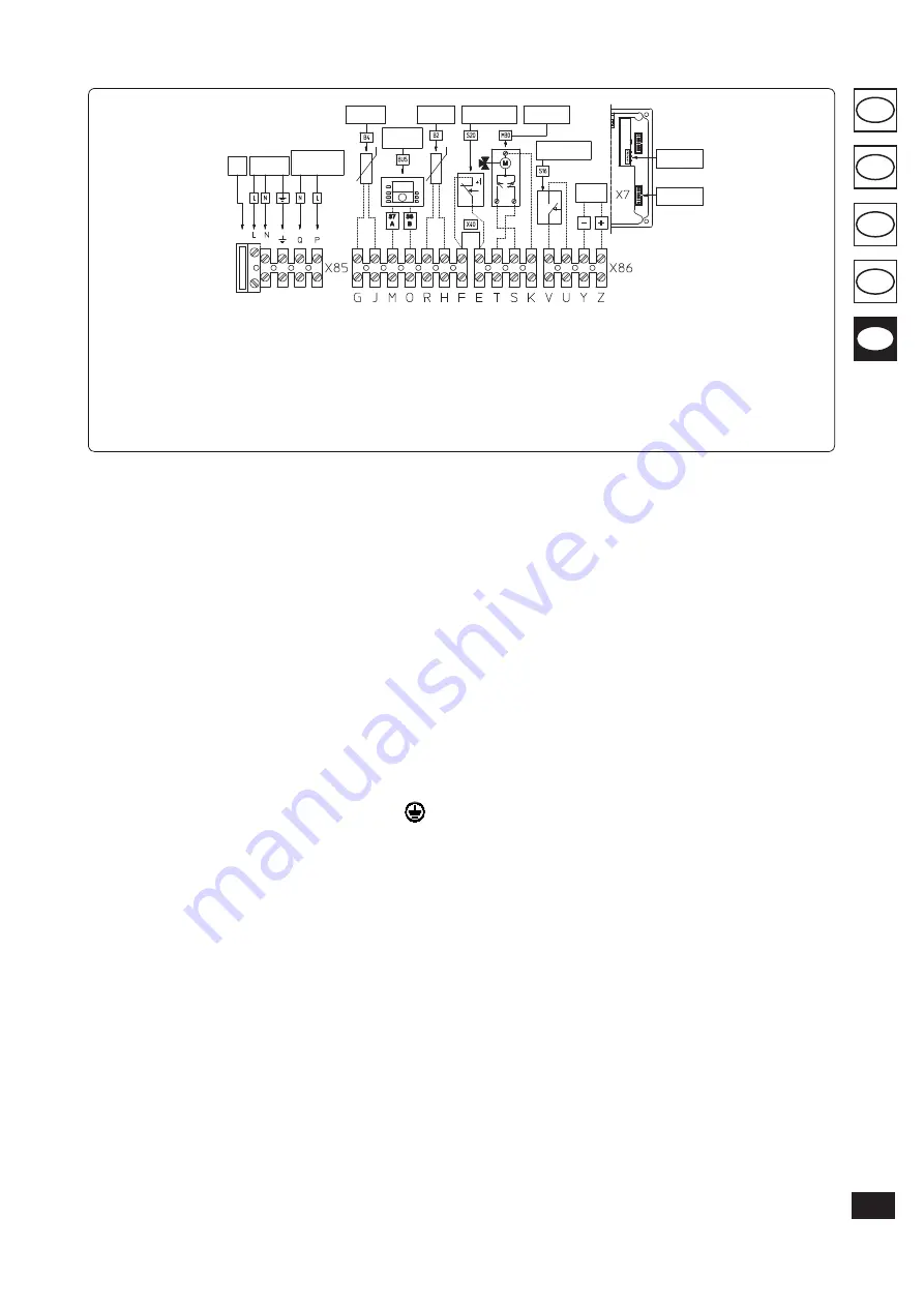
Fig. 1-4
Key:
1 - Fuse 2AF
2 - 230 Vac - 50 Hz
3 - External pump (optional) Max.
1A
4 - External probe (Optional)
5 - Heat adjuster (Optional)
6 - Boiler probe (Optional)
7 - Room Thermostat (Optional)
8 - 3-way valve (Optional)
9 - Summer Switch (Optional)
10 - Analogue input
11 - Clip in for cascade addresses
management
12 - Data download serial interface
117
TR
SI
RU
IE
CZ
Содержание VICTRIX 115 1 I
Страница 2: ......
Страница 145: ......
Страница 146: ...www immergas com This instruction booklet is made of ecological paper Cod 1 029592 Rev 15 031093 001 01 10 ...


