background image

ES

CZ

HU

SL

HR

102

IE

PL

IE

ES

103

CZ

HU

SL

HR

PL

Gas connection (Appliance category II

2H3+

).

Our boilers are built to operate on methane gas (G20) and 

LPG.   Feed piping must be the same as or larg er than the 

3/4"G  boiler  fi tting.  Before  making  the  gas  connection, 

carefully clean inside all the fuel feed system piping in order 

to remove any residuals that could impair good boiler ope-

ration. Also make sure the gas corresponds to boiler speci-

fi cations  (see boiler dataplate). If diff erent, the boiler must 

be con vert ed for operation with the other type of gas (see 

unit conversion in case of gas change). It is also im por tant to 

check the dynamic pressure of the gas supply (natural gas or 

LPG)  to be used for feeding the boiler which must conform, 

as insuffi  cient pressures can reduce generator power, causing 

the user in con ven ienc es. 

Ensure that the gas cock connection is carried out correctly, 

following the assembly sequence shown in the fi gure.  e 

gas supply pipe must be suitably dimensioned according to 

current standards in order to guarantee correct gas delivery to 

the boiler even in conditions of maximum gen er a tor output 

and to guarantee the unit’s performance (technical data).  e 

coupling system must conform to standards.

Gas quality.

  e unit is designed to operate with fuel gas free 

of impurities; otherwise, suitable fi lters should be installed 

ahead of the unit in order to re store fuel purity.

Storage tanks (in case of feed from LPG tank).

- New LPG storage tanks can contain residuals of inert gases 

(nitrogen) which weaken the mixture delivered to the unit, 

causing anomalous op er a tion.

- Due to the composition of the LPG mixture, lay er ing of 

the mixture’s components can occur during the period of 

storage in the tanks.  is can cause a change in the heating 

power of the mixture de liv ered to the unit, with subsequent 

variation in its performance.

Water connection.

 Before making the connections, all sy-

stem piping must be carefully cleaned to re move any residuals 

that could impair boiler effi    cien cy.  In order to prevent scaling 

in the heating system, the provisions contained in standard, 

con cern ing the treatment of water in heating systems for 

civil use, must be complied with. Water connections must be 

made in a rational way, using the connections on the boiler 

template.  e boiler safety valve outlet must be connected to 

a discharge funnel. Otherwise, the manufacturer declines any 

responsibility in case of fl ooding if the drain valve cuts in.

Electrical Connection

.  e Eolo Mini S boiler is de signed 

with IPX4D protection rating. Electrical safe ty of the unit is 

guaranteed when correctly connected to an effi  cient earthing 

system as specifi ed by cur rent safety standards.

Caution

: Immergas S.p.A. declines all liability for damage 

or physical injury caused by failure to con nect the boiler to 

an effi  cient earthing system or fail ure to observe reference 

standards.
Also ensure that the electrical installation cor re sponds to 

maximum absorbed power specifi cations as shown on the 

boiler dataplate.

Boilers are supplied complete with an “X” type pow er ca-

ble without plug.  e power plug must be con nect ed to a 

230V-50Hz mains with the correct pole sequence L-N and 

the earth connection; the mains must also be equipped with 

a multi-pole cir cuit break er with a contact opening gap of 

at least 3 mm. 

In the event of power cable replacement, contact for example 

an Authorised Immergas Service Centre for as sist ance.

 e power cable must be laid.

In the event of mains fuse replacement on the con trol card, 

use a 2A quick blow fuse. For the main pow er supply to the 

appliance, never use adapters, multiple sockets or extension 

leads.

N.W.

: when connecting the appliance, if the correct L-N 

polarity is not observed the boiler does not de tect the fl ame 

and inhibits start-up. Also in the same case, if the neutral 

is powered with residual voltage over 30V, the boiler will 

probably operate, but only temporarily. Measure the voltage 

readings with suit a ble tools; avoid the use of mains tester 

screw driv er. If the power supply is phase-phase type at 230V, 

to guarantee safe con di tions equivalent to existing con di tions 

when the boil er is powered with a Phase-Neu tral mains, an 

adaptor  kit  must  be  fi tted  on  the  boiler  for  Phase-Phase 

mains, available on request. Con tact an Authorised Immergas 

Service Centre for in stal la tion of the kit.

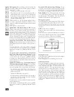
Room  thermostat  electrical  connection  On/Off .

  Eolo 

Mini S boilers are designed for use with an room thermo-

stat or chronothermostat On/Off . and clock programmer. 

If you have only one of these devices, connect to ter mi nals 

6 and 9 and remove jumper P1. Whereas if you have both, 

connect (TA) on terminals 8 and 9, and (CP) on terminals 

6 and 7, after removing P1.

Caution:

 Boiler pipelines must never be used to earth the 

electrical or telephone lines. Ensure elimination of this risk 

before making the boiler electrical con nec tions.

Installing air intake and fl ue exhaust ter mi nals.

Immergas  supplies  various  solutions  separately  from  the 

boiler for the installation of air intake and fl ue extraction, 

fundamental for boiler operation.

N.W.:  e boiler must be installed exclusively with an 

original Immergas air intake and fl ue ex trac tion system 

as specifi ed by standards.  is system is identifi able by 

a special iden ti fi  ca tion mark bearing the note: “not for 

con dens ing boilers”.

 e fl ue ducts have not to be near or in contact with infl am-

mable materials, and they have not to pass through buildings 

and walls made of infl ammable materials.
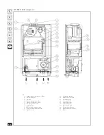
Key:

1 - Gas valve

2 - Flat seal

3 - Gas cock

4 - Gas pipe

Содержание EOLO Mini S

Страница 1: ...encias Podręcznik obsługi wraz z instrukcjami Návod k použití a upozornění Uputstva i napomene Priročnik z navodili in o pozorili Használati utasítás és figyelmeztetések Instruction booklet and warning ES CZ PL HR SL HU IE EOLO Mini S ...

Страница 2: ... przyszłość ponieważ zawiera ważne wskazówki dotyczące bezpieczeństwa instalacji eksploatacji i konserwacji Instalacja i konserwacja powinny być wykonane zgodnie z obowiązującymi normami według instrukcji producenta i przez wykwalifikowany personel tj osoby posiadające konkretną wiedzę techniczną z zakresu instalacji Niewłaściwa instalacja może spowodować obrażenia u ludzi i zwierząt a także szkod...

Страница 3: ...inõsül Az érvényes mûszaki jellegû jogszabályok szabványok és a jelen kézikönyvben leírt vagy egyéb módon a gyártó által átadott utasítások be nem tartásából származó beüzemelési mûködési és karbantartási hibák esetén a gyártónak semmilyen szerzõdéses vagy szerzõdésen kívüli felelõssége nincs az esetleges károkért és a berendezésre vonatkozó garancia megszûnik IE adekvatno osposobljenog i opremlje...

Страница 4: ... cm between the boiler casing and the sides of the cabinet is recommended Keep all flammable objects well away from the appliance paper cloths plastic polystyrene etc In the event of malfunctions faults or incorrect operation switch the appliance off immediately and contact a qualified technician e g from the Immergas Service centre to ensure use of original spare parts Never attempt to modify or ...

Страница 5: ...t safety standards Caution Immergas S p A declines all liability for damage or physical injury caused by failure to connect the boiler to an efficient earthing system or failure to observe reference standards Also ensure that the electrical installation corresponds to maximum absorbed power specifications as shown on the boiler dataplate Boilers are supplied complete with an X type power ca ble wi...

Страница 6: ...sed on the temperature of fluids conveyed through the ducts and therefore varies according to applications for air intake or flue exhaust Each component has a resistance corre sponding to a specific length in metres of pipe with the same diameter the so called equivalent length All boilers have a maximum resistance factor based on testing at 100 e maximum admissible resistance factor corresponds t...

Страница 7: ...t 16 5 m 1 Intake m 7 1m Intake and exhaust 46 m 2 8 Intake m 20m Intake and exhaust 6 m 0 4 Intake 2 6m Intake and exhaust 7 5 m 0 5 Intake 3 3m Exhaust 5 5 m Exhaust 7 0m Exhaust m 5 5m Intake m 14m Exhaust 2 0m Exhaust 2 5m m 2 8 m 3 5 m 2 8 Exhaust m 15m m 7 6 Exhaust 10 6m m 5 3 m 1 9 Intake and exhaust 32 Terminal complete with concentric horizontal Terminal complete with concentric horizont...

Страница 8: ...intake terminal Ø 80 m 1 with or without insulation 0 4 m 0 5 m Intake 2 3 Exhaust 3 0 8 m Intake 5 0 5 m Intake 3 0 2 m 0 3 m 0 2 m 0 1 m 2 2 m Sdoppiato parallelo Ø 80 da Ø 60 100 a Ø 80 80 Intake 3 8 m Exhaust 2 9 m 0 5 m Intake and exhaust 8 8 1 5 m 2 3 m Intake 16 9 m Exhaust 13 m Intake and exhaust 39 Terminal complete with concentric horizontal intake exhaust Ø 80 125 6 5 m Intake 14 8 m Ex...

Страница 9: ...ore the intake and exhaust duct Selection of a suitable diaphragm depends on the type of ducting used and maximum length calculations can be made using the values in the tables below N W Diaphragms are supplied as standard with the boi ler e values for maximum length are considered with 1 metre of exhaust pipe and the remaining on intake DIAPHRAGM Duct length in metres Ø 60 100 vertical Ø 41 5 Fro...

Страница 10: ...xhaust kit Ø 80 125 Kit assembly install the bend with flange 2 on the central hole of the boiler taking care to insert the seal 1 and tighten with the screws supplied in the kit Fit the adapter 3 with the male section smooth in the female section of the bend 2 with lip seal to the end stop Fit the concentric terminal Ø 80 125 4 with the male section smooth in the female section of the adapter 3 w...

Страница 11: ...tings and concentric elbows Ø 80 125 To install snap fit extensions with other elements of the boiler assembly proceed as follows fit the concentric pipe or elbow with the male section smooth on the female section with lip seal to the end stop on the previously installed to ensure sealing efficiency of the couplings Caution if the exhaust terminal and or extension concen tric pipe needs shortening...

Страница 12: ... the pipe or elbow with the male section smooth on the female section with lip seal to the end stop on the previously installed to ensure sealing efficiency of the couplings Installation clearances e following figure shows the mi nimum installation clearances for the terminal separator kit Ø 80 80 in maximum admissible conditions Extensions for separator kit Ø 80 80 e maximum straight length witho...

Страница 13: ...nd cap 6 on terminal 7 Join the exhaust pipe 9 with the male section smooth in the female section of the bend 10 to the end stop ensuring that the washer 8 is already inserted for correct installation between the pipe and flue Snap fit extension pipe fittings and elbows To install snap fit extensions with other elements of the boiler assembly proceed as follows fit the concentric pipe or elbow wit...

Страница 14: ...ndensation in insulated exhaust Ø 80 pipes due to cooling via the wall the exhaust pipe length must be restricted to 12 metres e figure above illustrates a typical insulation application in which the intake pipe is short and the exhaust pipe very long over 5 m e entire intake pipe is insulated to prevent condensation of humid air in the boiler environment in contact with the cooled pipe conveying ...

Страница 15: ...d in current technical standards Fumes exhaust on natural draught appliances in open top closed environments In spaces closed on all sides with open tops ventilation pits light wells inner court yards etc direct discharge of fumes is allowed for natural or forced draught gas appliances with a heat output from 4 to 35 kW provided the specifications of current technical standardsare System filling O...

Страница 16: ...est e boiler is de signed for installation of system shutoff valves for insertion on delivery and return pipelines on the connection assem bly This kit is particularly useful as it enables draining of the boiler separately from the entire system N W in presence of By Pass kit the cocks must be instal led in the system and not in the boiler By pass kit on request If zone valves are installed on the...

Страница 17: ...al pressure socket 6 Fan safety pressure switch 7 Sealed chamber 8 NTC limit and regulation sensor 9 Termp overload safety thermostat 10 Expansion vessel 11 Combustion chamber 12 Automatic air vent valve 13 Circulating pump 14 3 bar safety valve 15 System drain valve 16 System filling valve 17 Flue extractor hood 18 Primary heat exchanger 19 Ignition detection electrodes 20 Burner ...

Страница 18: ...y of ducting or devices for flue extraction and relative accessories switch off the appliance and on comple tion of operations ensure that a qualified technician checks efficiency of the ducting or other devices Never clean the appliance or connected parts with easily flammable substances Never leave containers or flammable substances in the same environment as the appliance Caution use of compone...

Страница 19: ...lamps switched off this status remains until the burner is ignited and the circulation pump is activated indicator lamp 2 ON With the switch set to the heating regulation selector 5 is used to regulate the temperature of radiators rotate clockwise to increase the temperature and counterclockwise to decrease Boiler operation is now automatic Ignition block Red indicator lamp 3 ON Each time heating ...

Страница 20: ...rgent to clean the boiler casing Never use abrasive or powder detergents Decommissioning In the event of permanent shutdown of the boiler contact professional personnel for the procedures and ensure that the electrical water and gas supply lines are shut off and disconnected ...

Страница 21: ...ilation and or aeration of the boiler environment If any checks inspection give negative results do not start the boiler Room thermostat and clock programmer the boiler is designed for application of an room thermostat TA and of a clock programmer CP If you have only one of these devices connect to terminals 6 and 9 and remove jumper P1 Whereas if you have both connect TA on terminals 8 and 9 and ...

Страница 22: ... opening of the hood on the air venting valve see fig page 114 Ensure that system pressure and pre charge of the expansion vessel are within the set limits the per charge value for the expansion vessel must be 1 bar and system pressure between 1 and 1 2 bar Ignition block see pages 116 and 102 electrical connec tion Converting the boiler to other types of gas In the event of converting the boiler ...

Страница 23: ... modulating coil simply detach a faston turn the screw clockwise to increase pres sure and counterclockwise to decrease On completion of adjustment turn power on to the modulating coil Boiler minimum heat output pressure must be not be adjusted to less than the values given in the tables on page 122 according to the type of gas Heating power adjustment see figure page 121 Adjust the room heating p...

Страница 24: ...the rear boiler panel as shown in the figure Pull the casing forwards and up at the same time see figure to detach from the upper hooks 845 gas valve for Eolo Mini S Eolo Mini S electronic card Key 1 Coil 2 Minimum power adjustment screw 3 Maximum power adjustment screw 4 Gas valve outlet pressure point 5 Gas valve inlet pressure point 6 Protection hood 10 2A fuse 11 Slow lighting adjustment trimm...

Страница 25: ... than ten seconds Visually inspect to check for leakage of water or oxidation of relative couplings Check visually that the water safety drain valve is not blocked Check that the charge of the expansion vessel after dischar ging system pressure to the zero setting check via boiler pressure gauge is at 1 bar Check that the system static pressure in cold conditions and after system recharging via th...

Страница 26: ...mm w g 1 3 20 204 0 77 29 296 0 77 37 377 Heating circuit max operating pressure Heating circuit max operating temperature Heating temperature range Total expansion tank volume Expansion tank pre load Generator water capacity Head available with 1000 l h flow rate Full boiler Empty boiler weight bar C C l bar l kPa m w g kg kg 3 90 38 85 6 1 0 3 5 24 5 2 5 37 33 Electrical connection Rated absorpt...

Страница 27: ...www immergas com is instruction booklet is made of ecolo gical paper Cod 1 019370 Rev 15 014939 000 06 03 ...

Отзывы: