background image

11

7

INS

TALLER

US

ER

MAINTEN

AN

CE

 TECHNI

CI

AN

TECHNI

CAL

 D

AT

A

- MIN. - MAX. program (blue LED).

 The pump is distinguished 

by adjustable operating curves by positioning the selector in any 

point between the Min. and Max. positions, thereby satisfying 

any installation requirement (from a simple single-pipe to more 

modern and sophisticated systems) and always guaranteeing op-

timum performance. The precise working point can be selected 

in the entire field of use by gradually adjusting the speed.

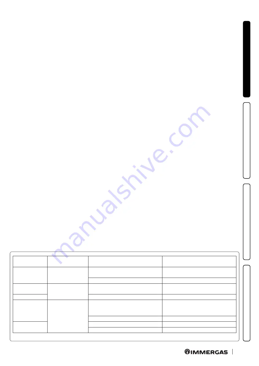
Real-time diagnostics:

 a lit LED (in various colours) provides 

information regarding the pump operating status, see fig. 7.

Possible pump release.

 The pump block is indicated by a fixed 

red LED switching on. Turn the selector up to the MAX. position, 

disconnect and reconnect the power to restart the automatic re-

lease process. The pump will then activate the procedure, which 

will last for a maximum of 15 minutes and the LED will flash upon 

each restart. It then turns blue for a few seconds and goes back to 

red if the attempt to restart is not successful. Once the process is 

complete, position the selector back on the desired curve and if 

the problem has not been resolved, perform the manual release 

procedure as described below.
- Disconnect the power to the boiler (the LED switches off). 
- Close the system flow and return and allow the pump to cool 

down.

- Empty the system circuit via the relative cock.
- Remove the motor and clean the impeller. 
- Once unblocked, remount the motor.
- Fill the primary circuit; restore boiler power and set the desired 

curve.

Attention:

 a scalding hazard is present due to high fluid tem-

peratures and pressures. 

Scalding hazard as a result of contact.

Circulating 

pump LED

Description

Diagnostics

Remedy

LED steady on

Pump 

noisy

Insufficient system pressure, circulating 

pump in cavitation

Restore correct thermal circuit pressure

Presence of foreign matter in the impeller Remove the motor and clean the impeller

Flashing white 

LED

Noises during cir-

culation of the heat 

transfer fluid

Presence of air in the system

Vent the system

LED steady on

Flow rate too high

Reduce rotation speed

LED off

The circulator does 

not work

Power outage

Ensure the boiler is correctly powered, 

ensure the circulator is correctly pow-

ered

Faulty circulating pump

Replace the circulating pump

Red LED

Rotor seized

Remove the motor and clean the impeller

Insufficient power supply voltage

Check boiler power supply voltage

1.9  SIZING THE SYSTEMS.

The flow temperatures to the various system zones may be re-

duced with respect to the boiler outlet temperatures, according 

to the mixture of the flow and return fluids inside the DIM ERP. 

In the event that the DIM ERP is used to feed Low-Temperature 

zones, check that the design parameters allow you to achieve a 

maximum surface temperature of the radiant floor in compliance 

with standard in force.

1.10  KITS AVAILABLE ON REQUEST.

• System cut-off cock kit (on request). The manifold is designed 

for the installation of system interception cocks, to be placed on 

the flow and return pipes of the connection assembly. This kit is 

particularly useful for maintenance as it allows the DIM ERP to 

be drained separately without having to empty the entire system.

• External probe kit.
• Safety thermostat kit.
The above-mentioned kits are supplied complete with instructions 

for assembly and use.

Содержание DIM 2 CONE ERP

Страница 1: ...TRIBUTION MANIFOLD DIM 2 ZONE ERP DIM 3 ZONE ERP DIM A BT ERP 1 direct zone and 1 mixed zone DIM A 2BT ERP 1 direct zone and 2 mixed zones IE Instructionsandrecommendations Installer User Maintenancetechnician 1 039170ENG ...

Страница 2: ......

Страница 3: ...he legislation in force the systems must be designed by qualified professionals within the dimensional limits established by the Law Installation and maintenance must be performed in compliance with the regulations in force according to the manufacturer s instructions and by professionally qualified staff intending staff with specific technical skills in the plant sector as envisioned by the Law I...

Страница 4: ... 3 7 DIM ERP connections to ON OFF room thermostats 27 3 8 DIM ERP connection to ON OFF room thermostats with shared zones 28 3 9 DIM ERP connections to room thermostats and C A R V2 on boilers other than Victrix Superior 2021 30 3 10 DIM ERP connections to room thermostats and C A R V2 on boilers other than Victrix Superior 2021 31 3 11 Victrix Superior 2021 DIM ERP connection with thermostats an...

Страница 5: ... technical regulations maintenance operations including scheduled periodic routine and special maintenance removal outdoors in the place for loading and transporting the appliancesandcomponents aswellastheireventualreplacement with appliances and or equivalent components Only professionally qualified companies are authorised to install the Immergas Multi System Distribution Manifold Installation m...

Страница 6: ...ow 2 G 3 4 F Zone flow 1 G 3 4 DIM 3 Zone ErP A Zone return 1 G 3 4 B Zone return 3 G 3 4 C Zone return 2 G 3 4 D Zone flow 2 G 3 4 E Zone flow 3 G 3 4 F Zone flow 1 G 3 4 DIM H LT ErP A High return temperature G 3 4 B Low return temperature G 1 E Low flow temperature G 1 F High flow temperature G 3 4 DIM H 2LT ErP A High return temperature G 3 4 B Zone1lowreturntemperature G1 C Zone2lowreturntemp...

Страница 7: ...nnection this network must also have a multi pole circuit breaker with class III over voltage category To protect from possible dispersions of DC voltage it is necessary to provide a type A differential safety device If the power supply cable is damaged it must be replaced by a special cable or assembly which are only available from the ma nufacturer or its After sales Service It is recommended to...

Страница 8: ...combined with the Victrix Superior range boiler new version 2021 the jumper on the RT connections of zone 1 managed remo tely must be maintained or used for contacts of zone shutter valves N B combined with boilers other than Victrix Superior new ver sion 2021 the jumper on the RT connections of the zone defined as main must be eliminated Installation layout of 2 homogeneous zones Key S20 1 Direct...

Страница 9: ...urn MZ2 Direct zone 2 flow MZ3 Direct zone 3 flow MZ1 Direct zone 1 flow Factory settings define zone 1 as the main zone See Fig 16 for electrical connection and Fig 17 for zones control unit setting DIM A BT ERP Installation diagram 1 direct zone and 1 mixed zone Key S20 1 Direct zone 1 room thermostat RT S20 2 Mixed zone 2 room thermostat RT 1 External probe optional 2 Boiler 3 Comando Amico Rem...

Страница 10: ...control the correct oper ating pressure Once these operations are complete make sure that the lever on the electric actuator is free from the manual lock position 1 8 CIRCULATION PUMP The pump is ideal for the requirements of each central heating system in a domestic and residential environment In fact the pump is equipped with electronic control that allows you to set advanced functions Adjustmen...

Страница 11: ...s present due to high fluid tem peratures and pressures Scalding hazard as a result of contact Circulating pump LED Description Diagnostics Remedy LED steady on Pump noisy Insufficient system pressure circulating pump in cavitation Restore correct thermal circuit pressure Presence of foreign matter in the impeller Remove the motor and clean the impeller Flashing white LED Noises during cir culatio...

Страница 12: ...dard setting D Head available to the system with circulator pump selector in position C3 E Head available to the system with circulator pump selector in position P2 F Head available to the system with circulator pump selector in position P1 G Circulator pump power with selector in position C4 standard setting H Circulator pump power with selector in position C3 I Circulator pump power with selecto...

Страница 13: ...a one way valve RZ1 Direct zone 1 return RZ2 Direct zone 2 return MZ2 Direct zone 2 flow MZ1 Direct zone 1 flow Key 1 Hydraulic manifold 2 Drain fitting 3 Zone 1 pump 4 Electrical connection box 5 Zone 1 Europa one way valve 6 Zone 2 pump 7 Zone 3 pump 8 Zone 3 Europa one way valve 9 Zone 2 Europa one way valve RZ1 Direct zone 1 return RZ3 Direct zone 3 return RZ2 Direct zone 2 return MZ2 Direct z...

Страница 14: ...3 Drain fitting 4 High temperature zone pump 5 Zone 2 low temperature safety thermostat 6 Zone 2 low temperature flow probe 7 Electrical connection box 8 Low temperature zone 1 3 way mixing valve 9 Low temperature zone 1 mixing valve motor 10 Low temperature zone 2 3 way mixing valve 11 Low temperature zone 1 safety thermostat 12 Low temperature zone 1 flow probe 13 Low temperature zone 1 circulat...

Страница 15: ...ice front lid is therefore prohibited The only operation that the user must perform is that of periodi cally checking the water pressure of the system in the boiler The boiler pressure gauge should read a value of between 1 and 1 2 bar If the pressure is below 1 bar with the circuit cool restore nor mal pressure via the filling valve located in the boiler see boiler instruction book N B close the ...

Страница 16: ...ard setting selector S27 Board setting selector T2 Zone control unit low voltage feeder Z1 Anti jamming filter 1 230 Vac 50 Hz power supply 2 Central heating request outlet to boiler or other DIM ERP 3 Central heating request inlet from other DIM ERP 4 ZonessignalstateoutletforotherDIMERP 5 ConnectiontoDIMERPsafetythermostat 6 ConnectionstoON OFFroomthermostats 7 Zones signal state inlet from boil...

Страница 17: ...t two or more zones are used the C A R V2 o Super C A R must be set with on off operation see instructions in the relative booklet The electrical connections of the RT inlets of the zones control unit relating to the zone controlled by the remote device must be left free if the DIM ERP is connected to boilers other than Victrix Superior new version 2021 N B combined with the Victrix Superior range...

Страница 18: ...d setting selector S27 Board setting selector T2 Zone control unit low voltage feeder Z1 Anti jamming filter 1 230 Vac 50 Hz power supply 2 Central heating request outlet to boiler or other DIM ERP 3 Central heating request inlet from other DIM ERP 4 Zones signal state outlet for other DIM ERP 5 ConnectiontoDIMERPsafetythermostat 6 ConnectionstoON OFFroomthermostats 7 Zones signal state inlet from...

Страница 19: ...t two or more zones are used the C A R V2 o Super C A R must be set with on off operation see instructions in the relative booklet The electrical connections of the RT inlets of the zones control unit relating to the zone controlled by the remote device must be left free if the DIM ERP is connected to boilers other than Victrix Superior new version 2021 N B combined with the Victrix Superior range...

Страница 20: ... S25 Board setting selector S26 Board setting selector S27 Board setting selector S28 P C B setting selector T2 Zone control unit low voltage feeder Z1 Anti jamming filter 1 230 Vac 50 Hz power supply 2 Central heating request outlet to boiler or other DIM ERP 3 Central heating request inlet from other DIM ERP 4 Zones signal state outlet for other DIM ERP 5 ConnectiontoDIMERPsafetythermostat 6 Con...

Страница 21: ... more zones are used the C A R V2 o Super C A R must be set with on off operation see instructions in the relative booklet The electrical connections of the RT inlets of the zones control unit relating to the zone controlled by the remote device must be left free if the DIM ERP is connected to boilers other than Victrix Superior new version 2021 N B combined with the Victrix Superior range boiler ...

Страница 22: ...flow regulation trimmer R13 Zone 3 low temperature flow regulation trimmer S25 Board setting selector S26 Board setting selector S27 Board setting selector S28 P C B setting selector T2 Zone control unit low voltage feeder Z1 Anti jamming filter 1 230 Vac 50 Hz power supply 2 Central heating request outlet to boiler or other DIM ERP 3 Central heating request inlet from other DIM ERP 4 Zones signal...

Страница 23: ... more zones are used the C A R V2 o Super C A R must be set with on off operation see instructions in the relative booklet The electrical connections of the RT inlets of the zones control unit relating to the zone controlled by the remote device must be left free if the DIM ERP is connected to boilers other than Victrix Superior new version 2021 N B combined with the Victrix Superior range boiler ...

Страница 24: ...ntrol unit the main ones being The Zones control unit will receive the following from the boiler Enabling zone mode Summer Winter mode etc Temperatures regulated on the boiler display for Low Temperature zones where possible External temperature probe connected to boiler Zone activation request from external devices connected to the boiler CAR Wireless probes etc The boiler will receive the follow...

Страница 25: ...etc Zone activation request from external devices connected to the boiler The boiler will receive the following from the Zones control unit Central heating request from zones The Zones control unit must be connected to its own external probe if necessary The mixed zone flow temperature must be adjusted on the zones control unit trimmers IMMERGAS MODELS WITH ZONE SIGNAL STATE OUTLET N B in this con...

Страница 26: ...ing them for example for post circulations or deactivating them by selecting the summer function on the boiler The Zones control unit must be connected to its own external probe if necessary The mixed zone flow temperatures must be adjusted on the Zones control unit trimmers Key 1 Zones control unit 2 External probe optional 3 Boiler ignition request the potential free contact of the boiler igniti...

Страница 27: ... thermostat On connecting the room thermostats it is necessary to eliminate the jumpers present on the X9 terminal board of the zones control unit If the Zones control unit is connected via BUS to Victrix Superior boilers 2021 the activation of the zones is determined by the closure of the Room Thermostats and by the program on the Boiler menu see boiler instruction booklet Key S20 1 Room thermost...

Страница 28: ... Every zone can be controlled by the relative room thermostat On connecting the room thermostats it is necessary to eliminate the jumpers present on the X9 terminal board of the zones control unit The room thermostat contacts can be replaced by those of the end run micro switches belonging to other zone valves inserted into the hydraulic circuit downstream from the zone pumps In the case of a sing...

Страница 29: ... 1 M30 1 3 Portion valve 3 of zone 1 S20 2 Room thermostat zone 2 S20 3 Room thermostat zone 3 S20 1 1 Portion 1 room thermostat of zone 1 S20 1 2 Portion 2 room thermostat of zone 1 S20 1 3 Portion 3 room thermostat of zone 1 RZ1 Direct zone 1 return RZ3 Direct zone 3 return RZ2 Direct zone 2 return MZ2 Direct zone 2 flow MZ3 Direct zone 3 flow MZ1 Direct zone 1 flow 1 Boiler 2 External probe opt...

Страница 30: ...zones control unit must be connected to the boiler via DIM BUS or a zone signal state to receive the zone activation request from CARV2 The CARV2 will control the zone set as the main one on the zones control unit In this example the zones control unit has set main zone 2 from switch 4 setting The jumper at the ends of X9 relating to the zone controlled by CARV2 must be eliminated On connecting th...

Страница 31: ...erior boilers 2021 can only control the request for zone 1 regardless of the section on the zones control unit If the zones control unit is connected to the Victrix Superior 2021 boiler the zone 1 RT jumper controlled by CAR must be kept on terminal board X9 of the zones control unit On connecting the room thermostats it is necessary to eliminate the jumpers on the X9 terminal board of the zones c...

Страница 32: ...trol unit On connecting the room thermostats it is necessary to eliminate the jumpers present on the X9 terminal board of the zones control unit The Zones control unit will receive the following from the boiler Enabling zone mode Summer Winter mode etc Temperatures adjusted on the boiler panel for mixed zones where possible External temperature probe connected to boiler Zone activation from boiler...

Страница 33: ...e 10 Zone 2 11 Zone 3 wireless room probe 12 Zone 3 13 DIM ERP 3 Zone 14 DIM ERP zones control unit The Zones control unit will receive the following from the boiler Enabling zone mode Summer Winter mode etc Temperatures adjusted on the boiler panel for mixed zones where possible External temperature probe connected to boiler Zone activation from boiler panel or Dominus if present The boiler will ...

Страница 34: ...0 Zone 2 11 Zone 3 wireless room probe 12 Zone 3 13 DIM ERP 3 Zone The Zones control unit will receive the following from the boiler Enabling zone mode Summer Winter mode etc Temperatures adjusted on the boiler panel for mixed zones where possible External temperature probe connected to boiler Zone activation from boiler panel or Dominus if present Zone 1 activation from CARV2 The boiler will rece...

Страница 35: ...ntral heating request of the second DIM to the first one using input X11 The first DIM ERP can receive the external probe value from the boiler The mixed zone flow temperatures of the first DIM ERP will be set on Superior series boilers connected via DIM BUS or on DIM ERP zones control unit trimmers when the same is connected to boilers different to Superior The second DIM ERP receives only the zo...

Страница 36: ... must be connected to its own external probe if necessary The mixed zone flow temperatures of the first DIM ERP must be regulated by its trimmers The second DIM ERP receives only the zone signal state from the first DIM ERP and it must be connected to its own external probe if required the relative mixed zone flow temperatures of the second DIM ERP must be adjusted on its trimmers Key 1 1st DIM ER...

Страница 37: ...rmostat 1st DIM ERP S20 2 1 Zone 1 room thermostat 2nd DIM ERP S20 2 2 Zone 2 room thermostat 2nd DIM ERP S20 2 3 Zone 3 room thermostat 2nd DIM ERP RZ1 Direct zone 1 return RZ3 Direct zone 3 return RZ2 Direct zone 2 return MZ2 Direct zone 2 flow MZ3 Direct zone 3 flow MZ1 Direct zone 1 flow 1 Boiler 2 External probe optional 3 External probe optional 4 DIM ERP zones control unit 5 First DIM ERP z...

Страница 38: ...ed to the boiler via zone signal state or DIM BUS where allowed The first DIM ERP can only receive the external probe value from the boiler if the DIM BUS communication is present The mixed zone flow temperatures of the first DIM ERP will be set on Superior boilers connected via DIM BUS or on DIM ERP zones control unit trimmers when the same is connected to boilers different to Superior or does no...

Страница 39: ... risk of pump blocking due to prolonged inactivity In the case of the H LT and H 2LT versions the same function also acts on the mixing valve in order to prevent and avoid the risk of blocking due to prolonged inactivity Post circulation System post circulation can be performed controlled by the boil er in the system zone selected as the main zone see installation layout Summer DHW functioning pri...

Страница 40: ...unctioning status and to indicate any anomalies The LEDs from 1 to 7 1 Fig 38 identify the activation of the relative relay LED H1 zone 1 activation high temperature LED H2 zone 2 activation low temperature LED H3 zone 3 activation optional LED H4 mixed zone 2 mixer opening LED H5 mixed zone 2 mixer closure LED H6 mixer opening zone 3 optional LED H7 mixer closing zone 3 optional The LED H11 signa...

Страница 41: ...pplication of the external probe Fig 40 which is available as an optional kit The probe can be connected directly to the manifold P C B or to the boiler electrical system and allows the max system flow temperature to be automa tically decreased when the external temperature increases in order to adjust the heat supplied to the system according to the change in external temperature The external pro...

Страница 42: ...E C 48 50 52 TM C 46 44 42 40 38 36 34 32 30 28 26 24 1 2 3 4 5 25 23 21 19 17 15 13 11 9 7 5 3 1 1 3 5 7 9 11 13 15 TE C INSTALLER USER MAINTENANCE TECHNICIAN TECHNICAL DATA Low temperature zone Correction law of the flow temperature depending on the external temperature and user adjustments of the central heating temperature TM Low temperature zone Flow Temperature TE External temperature 1 2 3 ...

Страница 43: ...king sure that the anomaly signalled via switch on of the LEDS H9 or H10 according to the cases on the P C B disappears Mixed zone flow temperature insufficient or too low It can depend on an incorrect regulation of the trimmer R12 or R13 present on the P C B from the blocked or broken mixing valve only for H LT and H 2LT version or on the temperature set on the lower boiler with respect to that r...

Страница 44: ...3 1 7 1 5 1 9 Total head available in direct zone with 1000 l h flow rate max kPa m c a 31 40 3 20 31 40 3 20 31 40 3 20 29 20 2 98 Total head available in mixed zone mixing valve open with 1000 l h flow rate max kPa m c a 30 30 3 10 30 30 3 10 Empty device weight kg 17 3 19 8 19 7 23 2 Full device weight kg 18 6 21 5 21 2 25 1 Electrical connection V Hz 230 50 230 50 230 50 230 50 Maximum input A...

Страница 45: ...45 ...

Страница 46: ...46 ...

Страница 47: ...47 ...

Страница 48: ...immergas com Immergas S p A 42041 Brescello RE Italy Tel 0522 689011 Fax 0522 680617 This instruction booklet is made of ecological paper Cod 1 039170ENG rev ST 002145 001 05 22 ...

Отзывы: