57
INS
TALLER
US
ER
MAINTEN
AN
CE TECHNI
CI
AN
2
1
1
P
2
P
f
f
e
c
P
a
MU
MU
AC
AF
R
M
GP
LP
AF
RU
2
1
13
14
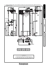
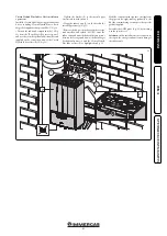
system flow; use the cock on the Basic Magis Pro
connection unit.
Attention:
in this installation it is essential to
leave the cap on the storage tank unit return
fitting of the indoor unit mounted.
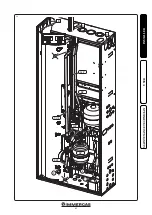
The DHW probe (
Fig. 14
) is to be inserted in the
specific seat "1" (
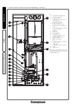
Ref. 17 Fig. 36
) when the DHW
electrical resistance is not present.
Vice versa, it must be inserted in seat "2"
(
Ref. 10 Fig. 36
).
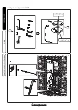
Tank Unit (a), Single-zone hydraulic unit (c)
and Magis Pro V2 Indoor Unit (P), as shown
in
Fig. 14
.
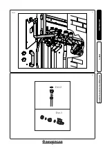
• Perform the connections in sequence, starting
from the pipes near the rear wall up to those
near the installer, remembering to insert the
special gaskets supplied.
N.B.:
the Magis Pro V2 Indoor Unit is supplied
with an interception cock to be placed on the
Magis Pro V2 Indoor Unit installation op-
erations.
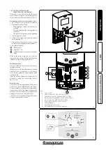
• Tighten the bracket (e) to the special upper
cross member with screws (f).
• Hang the indoor unit (P) on the bracket (e)
installed previously, (
Fig. 13
).
• Remove the by-pass pipe between the
storage tank unit flow and return (MU-
RU) from the indoor unit and make the
hydraulic connection between the Storage
Содержание BASIC MAGIS PRO
Страница 18: ...19 20 18 INSTALLATORE UTENTE MANUTENTORE Dett 1 Dett 2 ...
Страница 21: ...24 25 Dett 2 Dett 3 21 INSTALLATORE UTENTE MANUTENTORE Dett 1 ...
Страница 23: ...28 6 7 B B B 8 MP RP UCS EFS RP MP 9 23 INSTALLATORE UTENTE MANUTENTORE ...
Страница 44: ...IE ...
Страница 60: ...60 INSTALLER USER MAINTENANCE TECHNICIAN 19 20 Det 2 Det 1 ...
Страница 63: ...63 INSTALLER USER MAINTENANCE TECHNICIAN 24 25 Dett 2 Dett 3 Det 3 Det 2 Det 1 ...
Страница 65: ...65 INSTALLER USER MAINTENANCE TECHNICIAN 28 6 7 B B B 8 MP RP UCS EFS RP MP 9 ...
Страница 86: ...86 ...
Страница 87: ...87 ...


