background image

BASIC

MAGIS PRO

GRUPPO IDRONICO 

MONOZONA 

MONOTEMPERATURA CON  

UNITÀ BOLLITORE DA 160 

LITRI

SINGLE-TEMPERATURE 

SINGLE-ZONE HYDRONIC 

UNIT WITH  

160-LITRE STORAGE TANK 

UNIT

IT

Istruzioni e avvertenze

Installatore

Utente

Manutentore

Instructions and warnings

Installer

User

Maintenance technician

IE

Содержание BASIC MAGIS PRO

Страница 1: ...EMPERATURA CON UNITÀ BOLLITORE DA 160 LITRI SINGLE TEMPERATURE SINGLE ZONE HYDRONIC UNIT WITH 160 LITRE STORAGE TANK UNIT IT Istruzioni e avvertenze Installatore Utente Manutentore Instructions and warnings Installer User Maintenance technician IE ...

Страница 2: ...tamente compilata consente all Utente di usufruiredelleprestazionigratuiteprevistedallagaranziaconvenzionale IlCentroAssistenzaTecnicaAutorizzatoImmergasintervienedopouncongruotempo dalla chiamata dell Utente in funzione anche del livello oggettivo di criticità e dell anteriorità della chiamata la denuncia del vizio deve avvenire entro e non oltre 10 giorni dalla scoperta Trascorsi i termini di ga...

Страница 3: ...La manutenzione deve essere effettuata da personale tecnico abilitato il Servizio Assistenza Tecnica Autorizzato Immergas rappresenta in tal senso una garanzia di qualificazione e di professionalità L apparecchio dovrà essere destinato solo all uso per il quale è stato espressamente previsto Ogni altro uso è da considerarsi improprio e quindi potenzialmente pericoloso In caso di errori nell instal...

Страница 4: ...c Magis Pro con Victrix Hybrid Plus Optional 31 1 20Componenti principali kit abbinamento impianto solare termico Optional 32 1 21Schema idraulico Basic Magis Pro con Magis Pro V2 Optional 33 1 22Schema idraulico Basic Magis Pro con Magis Combo Plus V2 Optional 34 1 23Schema idraulico Basic Magis Pro con Victrix Hybrid Plus Optional 35 1 24Schema idraulico kit abbinamento impianto solare termico O...

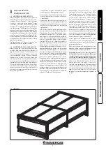
Страница 5: ...64 9 Prima di installare il prodotto è opportuno verificare che lo stesso sia giunto integro se ciò non fosse certo occorre rivolgersi immediatamente al fornitore Gli ele menti dell imballaggio graffe chiodi sacchetti di plastica polistirolo espanso ecc non devono essere lasciati alla portata dei bambini in quanto fonti di pericolo Nessun oggetto infiammabile deve trovarsi nelle vicinanze dell app...

Страница 6: ...LLATORE UTENTE MANUTENTORE 1 4 DIMENSIONI D INGOMBRO SOLAR CONTAINER PER INSTALLAZIONE BASIC MAGIS PRO IN ABBINAMENTO A MAGIS PRO 4 6 9 V2 E VICTRIX HYBRID PLUS Altezza mm Larghezza mm Profondità mm 2200 950 350 ...

Страница 7: ... fumi frontale e posteriore Rif B Allacciamento fumi superiore Attenzione Per Victrix Hybrid Plus con il kit concentrico 60 100 è sempre necessario utilizzare anche il kit tronchetto flangiato 60 100 Victrix Hybrid Plus Altezza Collegamento Victrix Hybrid Plus 98 Scarico 80 107 Concentrico 111 Aspirazione 80 ...

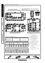
Страница 8: ... zona 2 RC Ricircolo sanitario escluso versione Combi SC Scarico condensa V Allacciamento elettrico VCR Allacciamento elettrico comando remoto VS Valvola di scarico 3 bar ALLACCIAMENTO LATERALE DESTRO ALLACCIAMENTO POSTERIORE ALLACCIAMENTO POMPA DI CALORE UNITA ESTERNA Per dettagli quote vedi Fig 2 ALLACCIAMENTO INFERIORE Attenzione le quote riportate fanno riferimento agli adesivi applicati all i...

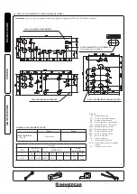
Страница 9: ...AGIS PRO IN ABBINAMENTO A MAGIS COMBO PLUS 4 6 9 V2 Altezza mm Larghezza mm Profondità mm 2200 950 430 ATTENZIONE Con il kit concentrico 60 100 utilizzare la foratura D 110 mm superiore Il collegamento dal lato sinistro del Solar Container Combo è possibile solo con l aspirazione scarico del separatore Ø 80 80 ...

Страница 10: ...MZ1 Mandata impianto zona 1 MZ2 Mandata impianto zona 2 RZ1 Ritorno impianto zona 1 RZ2 Ritorno impianto zona 2 RC Ricircolo sanitario SC Scarico condensa V Allacciamento elettrico VCR Allacciamento elettrico comando remoto VS Valvola di scarico 3 bar ALLACCIAMENTO LATERALE DESTRO ALLACCIAMENTO POSTERIORE ALLACCIAMENTO INFERIORE Attenzione le quote riportate fanno riferimento agli adesivi applicat...

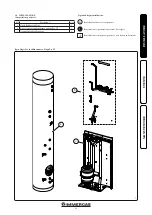
Страница 11: ...ne sequenziale operazione da svolgere Identificazione componente generico o non fornito in dotazione a 1 A 1 9 INSTALLAZIONE Composizione pacchetto Rif Descrizione Q tà a Unità Bollitore 160 litri 1 b Kit accessori per abbinamento a Magis Pro V2 1 c Gruppo Idraulico Monozona 1 Basic Magis Pro in abbinamento a Magis Pro V2 ...

Страница 12: ...azione Prima di iniziare l installazione del pacchetto è necessario aprire completamente il Solar Container aprendo il portello A e bloccandolo per evitare che crei intralcio durante le fasi suc cessive di installazione Asportare inoltre ilcoperchio B edilcoperchio laterale C ...

Страница 13: ...RE Inserire e bloccare la fascia contenimento unità bollitore d2 sulle viti predisposte sul Solar Container Inserire l unità bollitore a all interno del Solar Container con la flangia posizionata sul lato destro ed in basso come raffigurato in Fig 10 ...

Страница 14: ...l posiziona mento del gruppo idraulico avvitando viti auto perforanti d7 attraverso le forature predisposte sulla parte bassa del gruppo idraulico stesso Attenzione le viti di fissaggio d6 e d7 sono presenti nel kit accessori per abbinamento a Magis Pro V2 Appendere il gruppo idraulico c alla staffa centrale predisposta sul Solar Container As sicurare il posizionamento del gruppo idrau lico avvita...

Страница 15: ...g 14 Eseguire i collegamenti in sequenza iniziando dalle tubazioni più vicine al muro posteriore fino a quelle più vicine all installatore ricor dandosi di interporre le apposite guarnizioni fornite in dotazione N B l Unità Interna Magis Pro V2 viene fornita con rubinetto di intercettazione da posizionare sulla mandata impianto utilizzare il rubinetto presente nel gruppo allacciamento del Basic Ma...

Страница 16: ... installata Fig 15 Rimuovere il tubo by pass tra mandata e ritor no unità bollitore MU RU dall unità interna ed eseguire il collegamento idraulico tra Unità Bollitore a Gruppo idraulico monozona c e Unità Interna Magis Combo Plus V2 G come evidenziato in Fig 17 e 18 Eseguire i collegamenti in sequenza iniziando dalle tubazioni più vicine al muro posteriore fino a quelle più vicine all installatore...

Страница 17: ...17 1 2 3 18 Dett 3 Dett 4 a c G RU AF M MU R Dett 1 Dett 2 AC MU LP GP AF h 17 INSTALLATORE UTENTE MANUTENTORE Legenda 1 2 Forniti nel kit accessori 3 Presente in Magis Combo Plus ...

Страница 18: ...19 20 18 INSTALLATORE UTENTE MANUTENTORE Dett 1 Dett 2 ...

Страница 19: ...a traversa supe riore con viti f Appendere l unità interna P alla staffa E precedentemente installata Fig 21 Rimuovere il tubo by pass tra mandata e ritor no unità bollitore MU RU dall unità interna ed eseguire i collegamenti idraulici tra Unità bollitore a gruppo idraulico Basic Magis Pro c e Unità Interna Victrix Hybrid Plus P come evidenziato in Fig 23 Eseguire i collegamenti in sequenza inizia...

Страница 20: ... 22 a c G AF RHT MHT Dett 1 Dett 2 Dett 3 AC MU MU RU M AF h V Z 23 MHT RHT DOMUS CONTAINER MHT RHT SOLAR CONTAINER 20 INSTALLATORE UTENTE MANUTENTORE Basic Magis Pro in abbinamento a Victrix Hybrid Plus ...

Страница 21: ...24 25 Dett 2 Dett 3 21 INSTALLATORE UTENTE MANUTENTORE Dett 1 ...

Страница 22: ...a 4 che va avvolta allo stesso e fatta passare dietro l apposita squadretta 2 Procedere con i collegamenti idraulici del kit Fig 28 Eliminare i due tappi presenti sull unità bol litore per effettuare i collegamenti dei relativi tubi UCS e EFS Collegare il rubinetto di intercettazione 6 sullo scambiatore a piastre interponendo la relativa guarnizione piana Collegaresecondolaseguentesequenzatuttii t...

Страница 23: ...28 6 7 B B B 8 MP RP UCS EFS RP MP 9 23 INSTALLATORE UTENTE MANUTENTORE ...

Страница 24: ...A Valvola di sicurezza 8 bar sanitario Avvitare il raccordo d9 sulla valvola di sicu rezza Avvitare l imbuto d10 al raccordo d9 e convogliare l uscita alla rete fognaria Valvola di sicurezza 3 bar impianto Collegare il tubo al silicone d11 allo scarico del la valvola di sicurezza presente nell unità interna vedere relativo libretto istruzioni e dopo averlo tagliato a misura inserirlo all interno d...

Страница 25: ...l parametro visualizzato al numero 5 5 Temperatura dei diversi sensori o valore del parametro visualizzato sotto al numero 4 A Descrizione tastierino Tasto Più Meno Tasto di conferma o tasto di navigazione nel menu OK N B sulla schermata principale è possibile scegliere il sensore che deve essere sempre visua lizzato premere il tasto OK per visualizzare il sensore desiderato Menù installazione Pre...

Страница 26: ...ank1 e la temperatura del collettore è scesa di 10 C la pompa si attiva per raffreddare il serba toio attraverso collettori La pompa si spegnerà quandolatemperaturadell acquascendeallivello di impostazione tkM1 o quando la differenza tra la temperatura della serie di collettori e del serbatoio è inferiore a 2 C Protezione antigelo Parametro FrEZ valore di default off Questa opzione mantiene la tem...

Страница 27: ...e è esclusivamente indicativa Temperatura minima 5 C L elettronica dell unità interna è dotata di serie di una funzione antigelo che provvede a mettere in funzione la resistenza elettrica quando la tempe ratura all interno del Solar Container o Domus Container scende sotto i 4 C La funzione antigelo è però assicurata soltanto se l unità interna è correttamente allacciata al circuito elettrico e co...

Страница 28: ...sione 8 l sanitario 9 Resistenza elettrica integrativa acqua calda sanitaria 1 5 kW optional 10 Sonda sanitario 11 Anodo sacrificale 12 Unità Bollitore 13 Resistenza elettrica integrativa impianto da 3 kW optional 14 Unità Interna Magis Pro V2 15 Valvola miscelatrice circuito sanitario 16 Termometro temperatura mandata zona 2 zona diretta 17 Sonda sanitario con resistenza elettrica sanitario 18 By...

Страница 29: ...Valvola di sicurezza 8 bar 5 Rubinetto intercettazione vaso sanitario 6 Flangia unità bollitore 7 Termostato antigelo 8 Scatola allacciamento kit antigelo 9 Vaso espansione 8 l sanitario 10 Sonda sanitario 11 Unità Bollitore 12 Unità Interna Magis Combo Plus V2 13 Valvola miscelatrice circuito sanitario 14 By pass 15 Termometro temperatura mandata zona 1 zona diretta 16 Rubinetto gas 17 Valvola un...

Страница 30: ...NSTALLATORE UTENTE MANUTENTORE ATTENZIONE Il collegamento dal lato sinistro del Solar Con tainer Combo è possibile solo con lo scarico del kit separatore D 80 80 e con aspirazione a destra posteriore anteriore ...

Страница 31: ...etto intercettazione vaso sanitario 5 Flangia unità bollitore 6 Termostato antigelo 7 Scatola allacciamento kit antigelo 8 Vaso espansione 8 l sanitario 9 Sonda sanitario 10 Anodo sacrificale 11 Unità Bollitore 12 Unità Interna Victrix Hybrid Plus 13 Rubinetto di riempimento 14 Valvola miscelatrice circuito sanitario 15 By pass 16 Valvola unidirezionale 17 Termometro temperatura mandata zona 2 zon...

Страница 32: ...ORE 1 20 COMPONENTI PRINCIPALI KIT ABBINAMENTO IMPIANTO SOLARE TERMICO OPTIONAL Legenda 1 Vaso d espansione 2 Centralina solare 3 Scambiatore a piastre 4 Gruppo circolazione 5 Valvola di sicurezza 6 Tanica 7 Rubinetto di intercettazione ...

Страница 33: ...mostato antigelo 14 Rubinetto di svuotamento unità bollitore 15 Rubinetto intercettazione vaso sanitario AC Uscita acqua calda sanitaria AF Entrata acqua fredda sanitaria MZ2 Mandata impianto zona diretta RZ2 Ritorno impianto zona diretta Legenda 1 Unità Bollitore 2 Unità esterna 3 Unità Interna Magis Pro V2 4 By pass 5 Resistenza elettrica integrativa impianto da 3 kW optional 6 Sonda sanitario 7...

Страница 34: ...rezionale 11 Valvola di sicurezza 8 bar 12 Termostato antigelo 13 Rubinetto di svuotamento unità bollitore 14 Rubinetto intercettazione vaso sanitario G Gas AC Uscita acqua calda sanitaria AF Entrata acqua fredda sanitaria MZ1 Mandata impianto zona diretta RZ1 Ritorno impianto zona diretta Legenda 1 Unità Bollitore 2 Unità esterna 3 Unità Interna Magis Combo Plus V2 4 By pass 5 Rubinetto di interc...

Страница 35: ...litore MU Mandata Unità Bollitore RR Riempimento impianto SC Scarico condensa R Ritorno impianto M Mandata impianto MHT Mandata da pompa di calore RHT Ritorno a pompa di calore AC Uscita acqua calda sanitaria AF Entrata acqua fredda sanitaria MZ2 Mandata impianto alta temperatura RZ2 Ritorno impianto alta temperatura Legenda 1 Unità Interna Victrix Hybrid Plus 2 Unità Esterna Audax DK4 3 Pannello ...

Страница 36: ...o valvola di sicurezza 6 bar 4 Gruppo di circolazione solare 5 Rubinetto di intercettazione 6 Scambiatore a piastre 7 Sonda bollitore solare 8 Rubinetto di svuotamento 9 Rubinetto con filtro AC Uscita acqua calda sanitaria AF Entrata acqua fredda sanitaria MU Mandata unità bollitore RU Ritorno unità bollitore MP Mandata da pannelli solari RP Ritorno a pannelli solari ...

Страница 37: ... gratuitamente la verifica iniziale del sistema di cui al punto 2 1 del libretto necessaria per l attivazione della garanzia convenzionale Immergas Il certificato di verifica e garanzia viene rilasciato all utente 1 27 MESSA IN SERVIZIO DELL IMPIANTO GAS Per la messa in servizio dell impianto occorre fare riferimento al relativo libretto istruzioni dell unità interna installata 1 28 MESSA IN SERVI...

Страница 38: ...do del rubinetto di svuota mento 8 e aprire il rubinetto di scarico 3 La vite di regolazione del regolatore di portata 11 deve essere orientata orizzontalmente per garantire la chiusura della valvola a sfera inte grata Aprire la valvola a sfera con termometro 2 posizionato sopra la pompa 4 riempire il serbatoio della pompa di riempi mento con la quantità di glicole necessaria più una scorta minima...

Страница 39: ...è ne cessario scegliere la tipologia di funzionamento più adatta all impianto e selezionare la velocità nel range disponibile privilegiando il risparmio energetico Visualizzazione stato di funzionamento Fig 46 All avvio del circolatore il led 2 si accende di colore verde per circa 2 secondi poi segue un breve lampeggio a maggiore intensità per poi spegnersi durante il normale funziona mento Il led...

Страница 40: ...i tentativi di sblocco automatico oppure sbloccare manualmente l albero motore agendo sulla vite al centro della testata Se l anomalia persiste sostituire il circolatore R Y Y Y Y Situazione anomala il circolatore continua a funzionare bassa tensione di alimentazione Tensione fuori range 160 Vac Controllare l alimentazione elettrica R Y Y Y Y Anomalia elettrica Circolatore bloccato Il circolatore ...

Страница 41: ...ienza o della necessaria conoscenza purchè sotto sorveglianza oppure dopo che le stesse abbiano ricevuto istruzioni relative all uso sicuro dell apparecchio e alla comprensione dei pericoli ad esso inerenti I bambini non devono giocare con l apparecchio La pulizia e la manutenzione destinata ad essere effettuata dall utente non deve essere effettuata da bambini senza sorveglianza Ai fini della sic...

Страница 42: ...ù assistenza Termoregolazione riscaldamento come indi cato nel relativo libretto istruzioni 3 2 MANUTENZIONE ANNUALE Verificare l integrità dell anodo di magnesio dell unità bollitore Controllare la tenuta degli elementi di mon taggio viti bulloni tasselli elementi della struttura ecc Verificare che l impianto sia in buono stato Verificare visivamente l assenza di perdite di acqua e ossidazioni da...

Страница 43: ...ruppo idraulico pieno kg 25 85 Peso gruppo idraulico vuoto kg 24 35 Peso unità bollitore piena kg 188 92 Peso unità bollitore vuota kg 32 7 Dispersioni kW 24h 1 60 Psbsol W K 1 48 Valore EEI circolatore solare 0 20 Part 3 Protezione impianto elettrico apparecchio IPX5D vedi libretto istruzioni unità interna installata 3 5 SCHEDA DI PRODOTTO IN CONFORMITÀ AL REGOLAMENTO 812 2013 Per una corretta in...

Страница 44: ...IE ...

Страница 45: ...e originalspare partsandare specificallytraineddirectlybythe manufacturer General warnings All Immergas products are protected with suitable transport packaging The material must be stored in a dry place protected from the weather The instruction booklet is an integral and essential part of the product and must be given to the new user in the case of transfer or succession of ownership It must be ...

Страница 46: ...1 12Safety valve drain 66 1 13Condensate drain 66 1 14Electrical connection 66 1 15Solar control unit installation Optional 67 1 16Antifreeze protection 69 1 17Main components Basic Magis Pro with Magis Pro V2 Optional 70 1 18Main components Basic Magis Pro with Magis Combo Plus V2 Optional 71 1 19Main components Basic Magis Pro with Victrix Hybrid Plus Optional 73 1 20Main components solar heatin...

Страница 47: ...islation and in compliance with local technical regulations and the required technical procedures Before installing the product ensure that it is delivered in perfect condition if in doubt contact the supplier immediately Packing materials sta ples nails plastic bags polystyrene foam etc constitute a hazard and must be kept out of the reach of children Keep all flammable objects away from the appl...

Страница 48: ...k connection Thermal solar systems circuit connecting bracket Inertial storage tank connection Height mm Width mm Depth mm 2200 950 350 1 4 SOLAR CONTAINER OVERALL DIMENSIONS FOR BASIC MAGIS PRO INSTALLATION COMBINED WITH MAGIS PRO 4 6 9 V2 AND VICTRIX HYBRID PLUS ...

Страница 49: ...oncentric 111 Intake 80 Victrix Hybrid Plus Attention For Victrix Hybrid Plus with the 60 100 concentric kit it is always neces sary to also use the 60 100 flanged stub pipe kit Ref B Upper flue Flue gas connection Ref A Front and rear flue Flue gas connection 1 5 PRE SECTION DETAIL FOR FLUE CONNECTION ...

Страница 50: ... 2 REAR CONNECTION RIGHT HAND SIDE CONNECTION Key G Gas supply AC Domestic hot water outlet AF DHW Domestic hot water water inlet MHT Flow from heat pump RHT Return to heat pump MHT2 Flow from heat pump Victrix Hybrid Plus RHT2 Return to heat pump Victrix Hybrid Plus LP Chiller line liquid phase GP Chiller line gaseous phase MZ1 Zone 1 system flow MZ2 Zone 2 system flow RZ1 Zone 1 system return RZ...

Страница 51: ... CONNECTION ATTENTION Use the top hole D 110 mm with the 60 100 concentric kit Connection from the left side of the Solar Container Combo is only possible with the intake exhaust of the separator Ø 80 80 Height mm Width mm Depth mm 2200 950 430 1 7 SOLAR CONTAINER COMBO OVERALL DIMENSIONS FOR BASIC MAGIS PRO INSTALLATION COMBINED WITH MAGIS COMBO PLUS 4 6 9 V2 ...

Страница 52: ...et AF DHW Domestic hot water water inlet LP Chiller line liquid phase GP Chiller line gaseous phase MZ1 Zone 1 system flow MZ2 Zone 2 system flow RZ1 Zone 1 system return RZ2 Zone 2 system return RC DHW Domestic hot water recircula tion SC Condensate drain V Electrical connection VCR Remote control electrical connection VS 3 bar discharge valve 1 8 SOLAR CONTAINER COMBO CONNECTION TEMPLATE Connect...

Страница 53: ...mposition Ref Description Q ty a 160 litre storage tank unit 1 b Accessories kit for coupling to Magis Pro V2 1 c Single zone Hydraulic Unit 1 Installation drawings key Unmistakeable component identification Sequential identification of the operation to perform Identification of generic or not supplied component A 1 a ...

Страница 54: ...C A B during the following installation procedures Also remove the cover B and the side cover C Installation operations Before installing the pack open the Solar Container completely by opening door A and blocking it to prevent it from getting in the way ...

Страница 55: ...10 7 a Insert the storage tank unit a into the Solar Container with the flange positioned on the right hand side and at the bottom as shown in Fig 10 Insert and block the storage tank unit retaining strip d2 on the screws fitted on the Solar Container ...

Страница 56: ...ral bracket Fig 12 Attention the fixing screws d6 and d7 are found in the accessories kit for coupling to Magis Pro V2 N B in the event that the installer thinks it is necessary it is possible to secure the position of the hydraulic unit even further by using self tap ping screws d7 inserting them into the holes on the lower part of the hydraulic unit itself Bendthestrip d2 aroundthestoragetankuni...

Страница 57: ...Tank Unit a Single zone hydraulic unit c and Magis Pro V2 Indoor Unit P as shown in Fig 14 Perform the connections in sequence starting from the pipes near the rear wall up to those near the installer remembering to insert the special gaskets supplied N B the Magis Pro V2 Indoor Unit is supplied with an interception cock to be placed on the Magis Pro V2 Indoor Unit installation op erations Tighten...

Страница 58: ...o the special upper cross member with screws f Hang the indoor unit G on the bracket e installed previously Fig 15 Remove the by pass pipe between the storage tank unit flow and return MU RU from the indoor unit and make the hydraulic connection between the Storage Tank Unit a Single zone hydraulic unit c and Magis Combo Plus V2 Indoor Unit G as shown in Fig 17 and 18 MagisComboPlusV2IndoorUnitins...

Страница 59: ...NSTALLER USER MAINTENANCE TECHNICIAN 17 1 2 3 18 Dett 3 Dett 4 a c G RU AF M MU R Dett 1 Dett 2 AC MU LP GP AF h Key 1 2 Supplied in the accessories kit 3 Present in Magis Combo Plus Det 2 Det 1 Det 4 Det 3 ...

Страница 60: ...60 INSTALLER USER MAINTENANCE TECHNICIAN 19 20 Det 2 Det 1 ...

Страница 61: ...racket E installed previously Fig 21 Remove the by pass pipe between the storage tank unit flow and return MU RU from the indoor unit and make the hydraulic connections betweentheStoragetankunit a theBasicMagis Pro hydraulic unit c and the Victrix Hybrid Plus Indoor Unit P as highlighted in Fig 23 Victrix Hybrid Plus Indoor Unit installation operations Install the Victrix Hybrid by using the addit...

Страница 62: ...AINTENANCE TECHNICIAN b 22 a c G AF RHT MHT Dett 1 Dett 2 Dett 3 AC MU MU RU M AF h V Z 23 MHT RHT DOMUS CONTAINER MHT RHT SOLAR CONTAINER Det 2 Det 3 Det 1 Det 2 Det 3 Basic Magis Pro for coupling to Victrix Hybrid Plus ...

Страница 63: ...63 INSTALLER USER MAINTENANCE TECHNICIAN 24 25 Dett 2 Dett 3 Det 3 Det 2 Det 1 ...

Страница 64: ...el using the clip 4 that must be wrapped around it and passed behind the special bracket 2 Make the hydraulic connections of the kit Fig 28 Remove the two caps present on the storage tank unit make the connections of the relative pipes UCS and EFS Connecttheinterceptioncock 6 ontheplate heat exchanger by interposing the relative flat gasket seal Following the sequence below connect all the pipes t...

Страница 65: ...65 INSTALLER USER MAINTENANCE TECHNICIAN 28 6 7 B B B 8 MP RP UCS EFS RP MP 9 ...

Страница 66: ...of at least 13 mm The system connect ing the appliance to the drainage system must be carried out in such a way as to prevent freezing of the liquid contained in it Before product start up ensure that the condensate can be correctly removed Also comply with standards in force UNI 11071 with national and local regulations on discharging waste waters 1 10 GAS CONNECTION Make the gas connection of th...

Страница 67: ...ayed press the OK key to display the desired sensor Installation menu Press the OK key for 5 seconds to access the installation menu When you access the installation menu the first parameter Syst is displayed it is possible to select another parameter by pressing the OK navigation key Once the desired parameter is displayed it is possible to change the value using the keys or Block function To pre...

Страница 68: ... day or prevent damage to the solar liquid N B it is preferable not to use this function in very cold places to prevent using too much energy accumulated in the tank To activate the function press and select on Now you can adjust the Freezing setting FrZt parameter defaultvalue 10 C Adjusta ble between 20 C and 7 C with recommended value 3 C Display DiSP parameter default value OFF Back lighting f...

Страница 69: ...tion of the heating cable is purely indicative Minimum temperature 5 C Theelectronicsoftheindoorunitcomesstandard withanantifreezefunctionthat activatestheelec tric resistance when the temperature in the Solar Container or Domus Container falls below 4 C The antifreeze function is only guaranteed if the indoor unit is connected properly to the electrical circuit and is constantly powered the essen...

Страница 70: ... hot water integra tive electric resistance optional 10 DHW probe 11 Sacrificial anode 12 Storage tank unit 13 3 kW system integrative electric resistance optional 14 Magis Pro V2 Indoor Unit 15 DHW circuit mixing valve 16 Zone 2 flow temperature thermome ter direct zone 17 DHW probe with DHW electrical resistance 18 By pass 19 One way valve N B in the presence of DHW Domestic hot water electrical...

Страница 71: ...Storage tank unit flange 7 Antifreeze thermostat 8 Antifreeze kit connection box 9 8 l domestic hot water expansion vessel 10 DHW probe 11 Storage tank unit 12 Magis Combo Plus V2 Indoor Unit 13 DHW circuit mixing valve 14 By pass 15 Zone 1 flow temperature thermometer direct zone 16 Gas cock 17 One way valve 1 18 MAIN COMPONENTS BASIC MAGIS PRO WITH MAGIS COMBO PLUS V2 OPTIONAL ...

Страница 72: ... INSTALLER USER MAINTENANCE TECHNICIAN 38 ATTENTION Connection from the left side of the Solar Container Combo is only possible with the drain of the separator kit D 80 80 and with right rear front intake ...

Страница 73: ...ge 6 Antifreeze thermostat 7 Antifreeze kit connection box 8 8 l domestic hot water expansion vessel 9 DHW probe 10 Sacrificial anode 11 Storage tank unit 12 Victrix Hybrid Plus Indoor Units 13 Filling cock tap 14 DHW circuit mixing valve 15 By pass 16 One way valve 17 Zone 2 flow temperature thermome ter direct zone 18 Gas cock 1 19 MAIN COMPONENTS BASIC MAGIS PRO WITH VICTRIX HYBRID PLUS OPTIONA...

Страница 74: ...NANCE TECHNICIAN 40 Key 1 Expansion vessel Expansion tank 2 Solar control unit 3 Plate heat exchanger 4 Circulation unit 5 Safety valve 6 Can 7 Interception cock 1 20 MAIN COMPONENTS SOLAR HEATING SYSTEM COUPLING KIT OPTIONAL ...

Страница 75: ...resistance optional AC Domestic hot water outlet AF Domestic cold water inlet MZ2 Direct zone system flow RZ2 Direct zone system return 8 Mixing valve filter 9 DHW circuit mixing valve 10 DHW Domestic hot water 8 l expansion vessel 11 One way valve 12 8 bar safety valve 13 Antifreeze thermostat 14 Storage tank unit draining tap 15 Domestic hot water vessel shut off cock 1 21 HYDRAULIC DIAGRAM BASI...

Страница 76: ...t AF Domestic cold water inlet MZ1 Direct zone system flow RZ1 Direct zone system return 7 Mixing valve filter 8 DHW circuit mixing valve 9 DHW Domestic hot water 8 l expansion vessel 10 One way valve 11 8 bar safety valve 12 Antifreeze thermostat 13 Storage tank unit draining tap 14 Domestic hot water vessel shut off cock 1 22 HYDRAULIC DIAGRAM BASIC MAGIS PRO WITH MAGIS COMBO PLUS V2 OPTIONAL ...

Страница 77: ...C Condensate drain R System return M System flow MHT Flow from heat pump RHT Return to heat pump AC Domestic hot water outlet AF Domestic cold water inlet MZ2 High temperature system flow RZ2 High temperature system return 10 Mixing valve filter 11 Mixing valve 12 DHW Domestic hot water 8 l expansion vessel 13 Domestic hot water vessel shut off cock 14 8 bar safety valve 15 One way valve 16 Antifr...

Страница 78: ...unit return MP Flow from solar panels RP Return to solar panels Key 1 Storage tank unit 2 Solar expansion vessel 3 6 bar Safety valve assembly 4 Solar circulation unit 5 Interception cock 6 Plate heat exchanger 7 Solar storage tank probe 8 Draining cock tap 9 Cock Tap with filter 1 24 HYDRAULIC DIAGRAM SOLAR HEATING SYSTEM COUPLING KIT OPTIONAL ...

Страница 79: ...ing the hydraulic circuit and starting the system carry out the following checks make sure the safety devices are included and are operating properly particularly safety valve 6 bar expansion vessel thermostatic mixing valve present in the Basic Magis Pro check that there are no leaks in the hydraulic circuit make sure the air vent valve is positioned in the highest point of the circuit above the ...

Страница 80: ...be horizontal in order to guarantee clo sure of the integrated ball valve Open the ball valve with thermometer 2 positioned over the pump 4 fill the filling pump tank with the amount of glycol necessary plus a minimum stock to be left on the bottom of the tank in order to prevent air circulating inside the circuit 5 The filling phase must have minimum dura tion of 20 25 minutes This time is requir...

Страница 81: ...erating mode is always visible and indica ted by the 3 yellow LEDs 4 Info All the LEDs are off when the pump is not powered Press the button 1 to change operating mode Every time the button is pressed all the possible functions are scrolled cyclically according to the following table Circulating pump LED Description G Y Y Y G Constant curve speed 1 G Y Y Y G Constant curve speed 2 G Y Y Y G Consta...

Страница 82: ...ed mechanically The pump cannot restart automatically due to an anomaly Wait for the pump to make automatic release attempts or manually release the motor shaft acting on the screw in the centre of the head If the anomaly persists replace the pump R Y Y Y Y On Off Off On Off Abnormal situation the pump continues operating low power supply voltage Voltage off range 160 Vac Check power supply R Y Y ...

Страница 83: ...terminal if fitted is not blocked If temporary shutdown of the appliance is re quired proceed as follows a drain the heating system if antifreeze is not used b shut off all electrical water and gas supplies if the latter is present In the case of work or maintenance to structures located in the vicinity of ducting or devices for flue extraction and relative accessories switch off the appliance and...

Страница 84: ...BE An external probe optional can be connected to the Magis Pro V2 or Magis Combo Plus V2 indoor units see the relevant instruction booklet for the connection For the Victrix Hybrid Plus the external probe is supplied as standard on the outdoor unit and the optional external probe cannot be connected to the indoor unit The correlation between the system flow tem perature and external temperature i...

Страница 85: ...essure bar 3 0 Maximum domestic hot water circuit pressure bar 8 0 Max central heating circuit temperature C 90 Max domestic hot water circuit operating temperature C 95 Domestic hot water adjustable temperature C DHW expansion vessel l 8 0 DHW expansion vessel pre charged pressure bar 3 0 Water content in the storage tank unit l 156 22 Full hydraulic unit weight kg 25 85 Empty hydraulic unit weig...

Страница 86: ...86 ...

Страница 87: ...87 ...

Страница 88: ...ducts that are correctly installed and used with respect to the Standards in force N B correct periodic maintenance is highly recommended Immergas TOOLBOX L App studiata da Immergas per i professionisti The App designed by Immergas for professionials Disponibile su Disponibile su Disponibile su immergas com Perrichiedereulterioriapprofondimentispecifici i Professionisti del settore possono anche a...

Отзывы: