background image

20

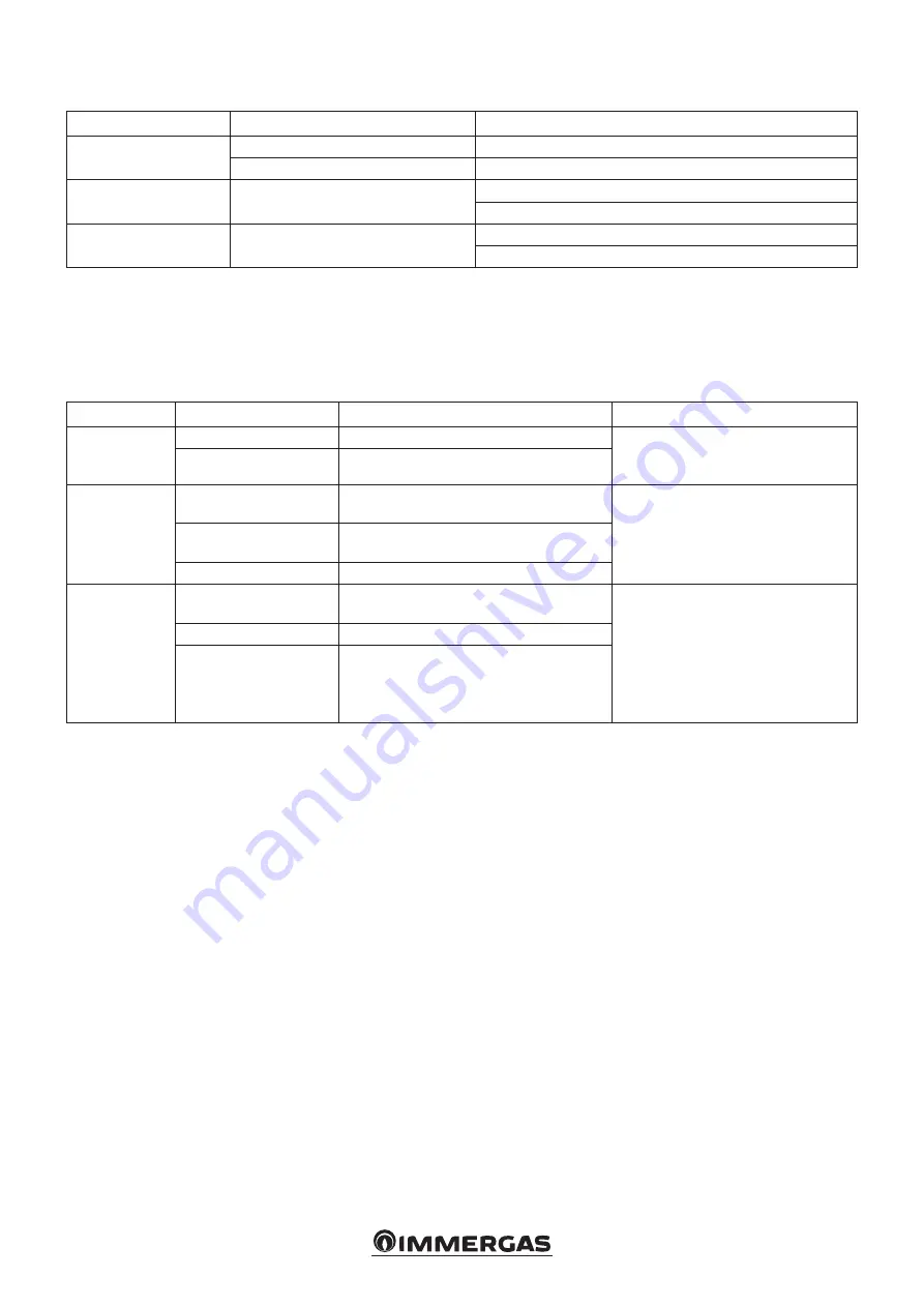
Troubleshooting.

Faults

Causes

Solutions

Pump not working with 

power supply on.

Faulty electrical fuse

Check the fuses

The pump is without voltage

Eliminate the power supply cut-off

The pump generates 

noise

Cavitation due to insufficient flow pres-

sure

Increase the system pressure within the allowed field
Check the head setting and eventually set a lower head

The building does not 

heat up.

Heat output of the radiant panels too 

low

Increase the delivery value
Set the adjustment mode to ΔP-c instead of ΔP-v

Diagnostics in real time

-  The anomaly LED indicates a fault.

-  The pump stops (depending on the fault), and performs 

cyclical attempts to restart.

LED

Faults

Causes

Solutions

It lights up red

Block

Rotor seized

Activate the manual restart or contact 

the Authorised Technical Service 

Centre

Contact/winding

Faulty winding

It flashes with 

red light

Under/Overvoltage

Feed side power supply voltage too low/

high

Check the mains voltage and operating 

conditions, ask the Authorised 

Technical Assistance Centre

Excessive module tem-

perature

Inside of the too hot module

Short-circuit

Motor current too high

It flashes with 

red/green light

Turbine operation

The hydraulic system of the pumps is fed 

but the pump has no mains voltage

Check the mains voltage, the water 

pressure/flow rate as well as the 

environmental conditions

Dry operation

Air in the pump

Overload

The motor runs with difficulty. The pump 

complies with the specifications (e.g. high 

module temperature). The number of 

revolutions is lower than normal operation

Manual restart

When a blockage is detected, the pump tries to automatically 

restart.

If the pump does not automatically restart:

-  Activate the manual restart by pressing the control key for 5 

seconds, then release.

-  The restart function starts and last max. 10 minutes.

-  The LEDs flash one after the other clockwise.

-  To interrupt, press the control key for 5 seconds.

Содержание 3.031483

Страница 1: ...COD 3 031483 KIT AGGIUNTIVO 2a ZONA MISCELATA PER TRIO PACK ADDITIONAL KIT 2nd MIXED ZONE FOR TRIO PACK IT Foglio istruzioni e avvertenze Instruction and warning book IE...

Страница 2: ...rientamento della valvola miscela trice come rappresentato nel dettaglio in Fig 3 collegare il tubo di mandata seconda zona 25 alla valvola miscelatrice 16 interponendo la guarnizione di tenuta 11 e a...

Страница 3: ...3 2 4 3 1 1 2 Legenda 1 Raccordo di scarico 2 Accumulo 3 Tappo 4 Tappo TRIO PACK IN SOLAR O DOMUS CONTAINER TRIO PACK CON KIT 2A ZONA MISCELATA IN SOLAR O DOMUS CONTAINER...

Страница 4: ...x2 12 1 Tubo ritorno impianto seconda zona 13 1 Coibentazione con velcro 14 1 Coperchio motore tre vie 15 1 Motore valvola miscelatrice 16 1 Valvola miscelatrice 17 1 Coibentazione valvola miscelatric...

Страница 5: ...e il connettore della sonda di mandata 2 e del termostato sicurezza 3 Collegare il circolatore 5 al connettore 1 Collegare il connettore della valvola miscela trice a 3 vie 4 N B avvolgere i raccordi...

Страница 6: ...a bassa temperatura M10 2 Circolatore zona 2 M31 2 Valvola miscelatrice zona 2 1 Chiuso 2 Comune 3 Aperto 4 Pannello principale Legenda codici colori BK Nero BL Blu BR Marrone G Y Verde Giallo GY Grig...

Страница 7: ...la possibilit di avere fastidiosi rumori di flusso d acqua nelle condutture nelle valvole e nei radiatori Condizioni ottimali di benessere termico e di benessere acu stico Prevalenza costante P C Il...

Страница 8: ...lgimento Avvolgimentodifettoso Lampeggiacon lucerossa Sotto sovratensione Tensionedialimentazionelatoalimentazi onetroppobassa alta Controllarelatensionedireteele condizionid impiego richiedereil Cent...

Страница 9: ...70 10 A X1 Y1 Y2 MIN MIN MAX M AX B Prevalenza disponibile all impianto zona 1 diretta velocit fissa Prevalenza disponibile all impianto zona 1 diretta prevalenza proporzionale Legenda A Prevalenza di...

Страница 10: ...Y1 Y2 MIN MIN MAX MAX B Prevalenza disponibile all impianto zona 1 diretta prevalenza costante Prevalenza disponibile all impianto zona 2 miscelata velocit fissa valvola miscelatrice aperta Legenda A...

Страница 11: ...AX B Prevalenza disponibile all impianto zona 2 miscelata prevalenza proporzionale valvola miscelatrice aperta Prevalenza disponibile all impianto zona 2 miscelata prevalenza costante valvola miscelat...

Страница 12: ...alvola unidirezionale 16 Filtro ispezionabile optional 17 Filtro ispezionabile 18 Termostato antigelo 19 Valvola di sicurezza 8 bar 20 Rubinetto di svuotamento bollitore 21 Rubinetto intercettazione v...

Страница 13: ...14 Valvola unidirezionale 15 Filtro ispezionabile optional 16 Filtro ispezionabile 17 Termostato antigelo 18 Valvola di sicurezza 8 bar 19 Rubinetto di svuotamento bollitore 20 Rubinetto intercettazi...

Страница 14: ...ented in detail in Fig 3 Connectthesecondzonedeliverypipe 25 tothemixingvalve interposing the sealing gasket 11 and to the accumulation 2 interposing the sealing gasket 6 pre mount the safety thermost...

Страница 15: ...15 2 2 4 3 1 1 TRIO PACK IN SOLAR OR DOMUS CONTAINER TRIO PACK WITH 2nd MIXED ZONE KIT IN SOLAR OR DOMUS CONTAINER Key 1 Drain fitting 2 Accumulation 3 Cap 4 Cap...

Страница 16: ...y thermostat 10 2 Fixing screws 11 3 Gasket 30x22x2 12 1 Second zone system return pipe 13 1 Velcro insulation 14 1 Three way motor cover 15 1 Mixing valve motor 16 1 Mixing valve 17 1 Mixing valve in...

Страница 17: ...t Connect the cables in the electrical panel of the Indoor Unit as shown in Fig 5 Lower the wiring coming out of the electri cal panel until it can be secured through the clamps 6 Connect the connecto...

Страница 18: ...E7 2 Low Temperature safety thermostat M10 2 Zone 2 pump M31 2 Zone 2 mixing valve 1 Close 2 Common 3 Open 4 Main panel Colour code key BK Black BL Blue BR Brown G Y Green Yellow GY Grey OR Orange W...

Страница 19: ...s valves and radiators is eliminated by reducing the head Optimal conditions for thermal comfort and acoustic well being Constant head P C The circulator pump maintains the pressure level head constan...

Страница 20: ...ng Itflasheswith redlight Under Overvoltage Feedsidepowersupplyvoltagetoolow high Checkthemainsvoltageandoperating conditions asktheAuthorised TechnicalAssistanceCentre Excessive module tem perature I...

Страница 21: ...40 60 80 10 30 50 70 10 A X1 Y1 Y2 MIN MIN MAX M AX B Total head available to the system of zone 1 direct fixed speed Total head available to the system of zone 1 direct proportional head Key A Total...

Страница 22: ...80 10 30 50 70 10 A X1 Y1 Y2 MIN MIN MAX MAX B Total head available to the system of zone 1 direct constant head Total head available to the system of zone 2 mixed fixed speed mixing valve open Key A...

Страница 23: ...0 50 70 10 A X1 Y1 Y2 MIN MIN MAX MAX B Total head available to the system of zone 2 mixed fixed speed mixing valve open Total head available to the system of zone 2 mixed constant head mixing valve o...

Страница 24: ...14 Direct zone circulator 15 One way valve 16 Inspectionable filter optional 17 Inspectionable filter 18 Antifreeze thermostat 19 8 bar safety valve 20 Tank unit draining valve 21 DHW vessel shut off...

Страница 25: ...r optional 13 Direct zone circulator 14 One way valve 15 Inspectionable filter optional 16 Inspectionable filter 17 Antifreeze thermostat 18 8 bar safety valve 19 Tank unit draining valve 20 DHW vesse...

Страница 26: ...26...

Страница 27: ...27...

Страница 28: ...ducts that are correctly installed and used with respect to the Standards in force N B correct periodic maintenance is highly recommended Immergas TOOLBOX L App studiata da Immergas per i professionis...

Отзывы: