Our policy is one of continued research and development. We therefore reserve the right to amend,
without notice, the specifications given in this document. © 2015 Norgren Automation Solutions, LLC.
05
10/15
P/N 00537UI REV: 004
C. Jaw Removal (cont.)
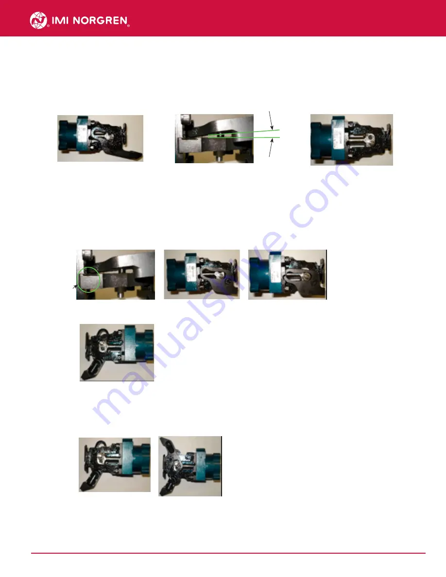
5. Remove bushing from lower jaw using a small flat screwdriver or hex key and set aside
for re-assembly. Lower jaw should be rotated completely down before removal. Lift up on
front of jaw by pad so there is an angle between jaw and frame. Remove lower jaw from
gripper.
5. Refer to step E-2 to set bumper position. Refer to step B for installing a Side Plate or
Indirect Sensor.
D. Jaw Replacement
1. For lower jaws
(10151,11105,11105-01, 11105-02, 11106, 11106-01, 11106-
02,11103,12978,12978-01, 12978-02, 12985, 12985-01, 12985-02):
Apply grease to
cam and inside of jaw. Angle new jaw so that tail of jaw goes in pocket of frame. Align
pivot hole with boss and drive pin with the bottom side of the cam slot. Carefully slide
jaw over boss and onto gripper. Replace bushing over pin and into cam. Apply grease
to outside of jaw.
4.
For upper jaws:
Apply grease to cam and inside of jaw. Replace bushing over drive
pin and onto gripper. Align hole in jaw with boss on frame and cam with bushing.
Slide jaw over boss and drive pin so that jaw rests on gripper. Apply grease to
outside of jaw.
2. Refer to step F for installing a Side Plate or Indirect Sensor.
3. Flip gripper over for top jaw installation
Tail of jaw
in pocket
Angle
User Instruction for PGS10 Series Gripper


