background image

4


Configuration Instructions 

Many iMcV-Modules have user-configurable features (e.g., FiberAlert, LinkLoss, Auto 
Negotiation, etc.).  Refer to the chart for information on available features on each 
module.  Instructions for configuring both managed (via an SNMP-compatible 
management application such as iView²) and unmanaged modules follow. 

Managed Modules 

To manage one or more iMcV-Modules, an SNMP agent must be present in the 
chassis. The iMediaChassis series, available in 3, 6 or 20 slots in both AC and DC, 
requires a separate SNMP Management Module.  To configure managed modules, 
install the module first, then configure it by using the management software.   


NOTE 

Management software overrides any hardware settings (e.g., jumper, switch, etc.), so make sure 
the module is configured through the software before beginning normal operation.  Until a 
module installed in a managed chassis is configured via the software, it will operate using the 
hardware configuration. 

Unmanaged Modules 

Before beginning installation of the iMcV-Modules, configure them for the desired 
features.  The chart below states the available features and settings for the iMcV-PIM 
and iMcV-LIM modules.  The board diagrams later in this manual show the 
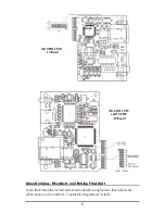
jumper/switch locations on the modules.  

Since there are no user-configurable 

features on the iMcV-S2MM/S2SM/M2MM modules, they can be installed straight 
from the box. 

After configuring the jumpers/switches for the desired settings, install the module and 
connect the appropriate cables (refer to the 

Installation

 section for more information). 

iMcV-Module Jumper/Switch Configuration Chart


Module Feature Jumper 

/Switch 

ON OFF 

Default 

IMcV-PIM 

TP/FO 

-10 Board 

Pulsing FiberAlert 

DIP Switch 1 

1-2 

2-3 

OFF 

FX LinkLoss 

JP2 

1-2 

2-3 

OFF 

TX LinkLoss 

JP3 

1-2 

2-3 

OFF 

Auto Negotiation 

DIP Switch 1 on S1 

see board 

see board 

ON 

iMcV-LIM 

TX/FX and 

TX/SSFX 

-30 Board 

FiberAlert* 

DIP Switch 2 on S1 

see board 

see board 

OFF 


Содержание iMcV-S2MM/1250

Страница 1: ...iMcV Modules Operation Manual Above illustrations are representative some minor differences may be present in actual product...

Страница 2: ...ructions and directions for a period of six 6 years after the original date of purchase This warranty is subject to the limitations set forth below At its option IMC Networks will repair or replace at...

Страница 3: ...arranty ii About the iMcV Modules 1 Installation 1 LED Operation 2 Configuration Instructions 4 Installation Troubleshooting 9 Specifications 9 IMC Networks Technical Support 10 Fiber Optic Cleaning G...

Страница 4: ...rent wavelengths 1310 nm and 1550 nm doubling the capacity of fiber Includes one RJ 45 connector and one SC fiber connector iMcV S2MM M2MM S2SM Protocol independent modules provide a single conversion...

Страница 5: ...reen when unit has power LNK RJ 45 Glows green if link is established on the twisted pair port located on RJ 45 ACT RJ 45 Glows amber when data is being passed on the twisted pair located on RJ 45 LNK...

Страница 6: ...data FA Glows green when FiberAlert is enabled FiberAlert is not available applicable on single strand versions of iMcV LIM LEDs on iMcV S2MM S2SM M2MM The LED functions on iMcV S2MM S2SM M2MM are as...

Страница 7: ...naged chassis is configured via the software it will operate using the hardware configuration Unmanaged Modules Before beginning installation of the iMcV Modules configure them for the desired feature...

Страница 8: ...t and Pulsing FiberAlert Some iMcV Modules include advanced troubleshooting features that help locate silent failures on the network Troubleshooting features include iMcV LIM TX FX and TX SSFX 30 Boar...

Страница 9: ...transmitters but normally has no way of knowing whether the cable to the other device is intact and the link pulses are reaching the other end The combination of FiberAlert and LinkLoss allows this in...

Страница 10: ...the loss of one strand of fiber If a strand is unavailable the IMC Networks device at the receiver end notes the loss of link The device will then stop transmitting data and start sending link pulses...

Страница 11: ...connection set the push button to a position that makes the twisted pair LNK link LED glow Auto Negotiation on iMcV LIM iMcV LIM Modules include the feature Auto Negotiation When Auto Negotiation is...

Страница 12: ...r by itself first make sure to have an appropriate fiber patch cable then follow these steps to test 1 Connect the media converter to the twisted pair device with a twisted pair cable 2 Loop a single...

Страница 13: ...10 IMC Networks Technical Support Tel 949 465 3000 or 800 624 1070 in the U S and Canada 32 16 550880 Europe Fax 949 465 3020 E Mail techsupport imcnetworks com Web www imcnetworks com...

Страница 14: ...between blasting with clean dry compressed air and flushing with methanol to remove particles of dirt Electrostatic Discharge Precautions Electrostatic discharge ESD can cause damage to any product a...

Страница 15: ...f separately from regular household waste It is the consumer s responsibility to dispose of this and all equipment so marked through designated collection facilities appointed by government or local a...

Страница 16: ...The information in this document is subject to change without notice IMC Networks assumes no responsibility for any errors that may appear in this document iMcV Modules is a trademark of IMC Networks...

Отзывы: