background image


B.3.4 

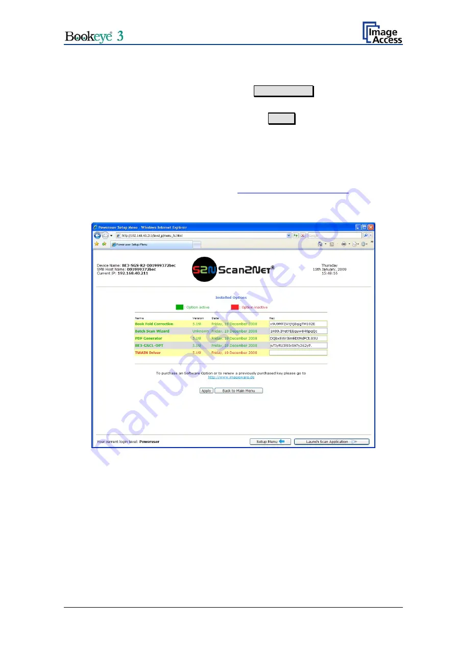
Install Options 

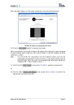
Locate the section 

Updates & Uploads

 and go to   Install Options  .  

All option keys displayed in green are valid and installed. A new key must be entered 
completely without blanks or spaces followed by the   Apply  button. If the key text does 
not turn green, the key is invalid or does not belong to this specific scanner or option. 


Note:  

Option keys are valid only for one option on a specific scanner denoted by its 
serial number.  
If a key is accidentally deleted it can always be obtained again at the Image 
Access Customer Service Portal 

http://service.imageaccess.de

 without extra 

cost. 


Picture 72: Install Option screen  


Setup and Assembly Manual 

Page 63 

Содержание bookeye 3

Страница 1: ...V Ve er rs si io on n R R1 1 Setup and Assembly Manual This device is compliant...

Страница 2: ...File BE3 R1 SetupAndAssembly H doc...

Страница 3: ...he user operation errors and you can control all functions from the beginning In addition please consider the following points Damages to your unit may have occurred during shipping Please check for d...

Страница 4: ...o ensure proper functionality best possible quality and performance of the device This device is a precise optical instrument and should be handled accordingly Section B describes the software setup I...

Страница 5: ...ional information concerning measurement of Auto Focus chapter B 2 2 to B 2 2 2 Differentiation between Chassis A and Chassis B H January 2009 New chassis version List of assembling material revised A...

Страница 6: ...bling the Components 18 A 2 1 Assembling the Camera Head to the Neck 18 A 2 2 Assembling Lamps and Camera to the Body Element 21 A 2 3 Assembling the Glass Plate 28 A 2 4 Setting the Initial Lamp Posi...

Страница 7: ...ocus Measurement with Glass Plate Closed 50 B 2 3 Scan Center 52 B 2 4 White Balance 53 B 2 4 1 Some Basic Information 53 B 2 4 2 White Balance with Glass Plate opened 55 B 2 4 3 White Balance with Gl...

Страница 8: ...Target 68 C 3 Recovery Function 69 C 3 1 Important Notes before recovering to Factory Defaults 69 C 3 2 How to Recover to Factory Defaults 69 C 4 Troubleshooting Matrix 71 C 5 Error Codes 73 D Techni...

Страница 9: ...ed screws 23 Picture 19 Body element cover opened 23 Picture 20 Position of gas spring fixture at right lamp 24 Picture 21 Fixing the lamp 24 Picture 22 Camera neck assembly 25 Picture 23 Front side 2...

Страница 10: ...cture 59 Auto focus measurement screen 51 Picture 60 Scan Center screen 52 Picture 61 Brightness Correction Factor screen 54 Picture 62 R G B controls 54 Picture 63 Glass plate positions for white bal...

Страница 11: ...Setup and Assembly Manual Page 11...

Страница 12: ...ent back in the original transport box to avoid transport damages The crates and the inserts have been designed and tested to withstand all impacts in accordance with the internationally recognized te...

Страница 13: ...ck below the reference folder and two manuals All parts are held in position by foam rubber elements Picture 2 Cardboard separator with lamps and neck Lamps 1 and 2 Reference folder 3 Picture 3 Refere...

Страница 14: ...in body and camera head box Two book cradle plates are attached to the scanner s main body Take the cardboard box out of the transport box The cardboard box contains the camera head and the short part...

Страница 15: ...amera neck at the scanner s body 8x and to fix the neck to the camera head 2x 4x Lens head Allen screws M4x10 Used to fix the cover of the scanner to the scanner s body 2x Hinges 2x Gas springs for th...

Страница 16: ...ensity across the scan area should be kept below 20 If the fluorescent lamps are powered by non electronic ballasts they will produce a flicker twice the frequency of the main power supply 100Hz or 12...

Страница 17: ...east three times the weight of the unit Also it should not shake or move to avoid image distortions If the table is too weak it can be attached to a solid wall to stabilize it A 1 2 4 Power outlet Ens...

Страница 18: ...a head must be inserted into the neck and must be guided through it One end of the neck and the end of the camera head element are cut at a corresponding angle Insert the cables at this end of the nec...

Страница 19: ...nment Picture 8 at both sides To ensure a proper angle alignment between the short neck and the long neck it is necessary to fasten the screws in the given order At first fasten the two Allen set scre...

Страница 20: ...elow in the following pictures Picture 11 Camera neck assembled at camera head Picture 12 Placing the cover on the neck Fasten the cover with two Allen screws M8x12 Use plastic washers with the screws...

Страница 21: ...out of the transport box must be done by two persons Picture 15 Two persons lift the device out of the transport box Place it on a suitable stable surface The bearing capacity of the table must exceed...

Страница 22: ...ly in a place where it cannot be broken Storing it in the transport box is recommended Insert eight Allen set screws M8x8 into the fastening elements where the transport Allen screws were removed Pull...

Страница 23: ...pening CAUTION Danger of injury Never put your fingers in the driving element openings Slide the body element cover approximately 300 mm 12 inch to the front side This will make the lamp holder bracke...

Страница 24: ...xture in the right lamp Note The definition of right side and left side always refers to the normal operating position i e from the front side of the scanner Picture 20 Position of gas spring fixture...

Страница 25: ...old the glass plate bearing Picture 22 Camera neck assembly Note It is recommended to perform the next steps with two persons One person holds and positions the camera neck while the second person han...

Страница 26: ...h matching colors Picture 25 Connector board with camera neck cables The connector for the flat ribbon cable has no colored label but is easily identified by its characteristic form Picture 26 Connect...

Страница 27: ...ver reaches the edge of the power supply Then release the cable and slide the body cover in its final position Picture 29 Body cover at edge of power supply Insert the screws in the following order 1...

Страница 28: ...d after approximately 30 seconds the display shows READY TO SCAN The book cradle plates are controlled by the eight buttons in the middle of the keyboard field Picture 30 Book cradle controller Press...

Страница 29: ...position of the axes at the right and left side of the glass plate Picture 32 T slot nut in corresponding position Slide a hinge on each axis Fix each hinge to the lamp with an Allen screw M8x12 Pict...

Страница 30: ...p and at the glass plate When the scanner is delivered the gas springs are already mounted to the lamps They only must be mounted to the glass plate To mount the gas springs to the glass plate remove...

Страница 31: ...onto the pin of the glass plate Picture 36 Gas spring mounted to glass plate Repeat the procedure with the second gas spring Finally insert the locking springs at both gas springs Picture 37 Locking s...

Страница 32: ...nly be done with the help of a second person Open the glass plate completely One person must hold the glass plate in this position while the second person opens the Allen set screw in the fixture slig...

Страница 33: ...a reference When a lamp is assembled into the scanner the light beam position relative to the home position switch is unknown To make known all positions of the above described electronic gear the fo...

Страница 34: ...ontrol field and simultaneously press the green START button Picture 40 Picture 40 Press the keys simultaneously The lamps light up and move to their start positions The display shows Adjust the light...

Страница 35: ...p is changed by pressing the left up down key of the keyboard The position of the right lamp is adjusted accordingly with the right up down key of the keyboard Picture 42 Up down key on right side of...

Страница 36: ...eave it in the correct position Picture 43 Light beam on right side of the book cradle Press the down key to move the light beam to the outside Press the up key to move the light beam to the inside Th...

Страница 37: ...on to save both lamp positions The sound OK will be played and the display shows Saving new positions The lamp positions will also be saved automatically when the time out period has passed without an...

Страница 38: ...the lamps will move at a higher speed than with the up key or down key only In this mode the lamps can be moved to their maximum positions for testing purposes The function of the home position switc...

Страница 39: ...refore the address has to be changed To perform this a connection to the scanner must be established First note all network settings in your local PC Then change the settings in your local PC to IP ad...

Страница 40: ...level Poweruser using the default password Poweruser Picture 46 Login level screen In the Base Settings section click at Network Configuration Picture 47 Poweruser Main Menu screen Page 40 Setup and...

Страница 41: ...cally Picture 48 Network configuration screen If the IP address has been changed the device has to be powered down and up again Change the settings of your local PC back to the previous network settin...

Страница 42: ...ensure that adjustments are made following the sequence below 1 Perform the Scan Start function This will synchronize the CCD main drive motor with the lamp motors so that the CCD is centered along th...

Страница 43: ...oftware Enter the IP address of the scanner in your browser to open the start menu Picture 49 Scan2Net Start screen In the start screen go to Setup Device Choose the login level Poweruser using the de...

Страница 44: ...to Adjustments Picture 51 Poweruser Main Menu screen Start in section Focus Scan Area Adjustments Select the appropriate menu items as described in the following paragraphs Picture 52 Adjustment Supp...

Страница 45: ...test target against the neck and center it as precisely as possible Any deviation of the test target in the horizontal direction from the ideal position will be present in all scans afterwards After t...

Страница 46: ...text the device is properly calibrated An error is always shown in red text and usually comes with an explanatory remark Picture 54 Scan Start results 1 Click the button New Values in the section Con...

Страница 47: ...ition This value measured with the selected glass plate position is the reference for all focus adjustments used later during e g book fold correction folder mode scanning or fixed focus scanning Pict...

Страница 48: ...The measurement starts Picture 56 Auto Focus measurement with open glass plate After the Autofocus function has completed the results will be displayed Values displayed in green indicate valid results...

Страница 49: ...5 Click the button New Values in the section Controls to repeat the measurement Or 6 Click the button Back to Adj Menu in the section Menu controls to return to the adjustments menu see Picture 52 Set...

Страница 50: ...described 9 Move the book cradles to the upper position Close the glass plate Note The position of the book cradles is verified If the book cradles are not in the upper position a Retry button instea...

Страница 51: ...ed by some explanatory remarks Note It is normal that the measurement will return different values each time the measurement is repeated The lens motor has a very high resolution and the best focal po...

Страница 52: ...d the scanner sees more area at the keyboard side of the scanning bed Since all scanners have some spare pixels that are not used the middle can be adjusted by defining a certain number of pixels at t...

Страница 53: ...lmost saturated output signal This assures that the largest density range possible is used After this adjustment is done the uneven light distribution on the CCD caused by the imbalance of the lamps t...

Страница 54: ...d way of changing the results is invoked if the individual R G B controls in the scanner application are used They allow changing the color temperature of the original reference scan Picture 62 R G B...

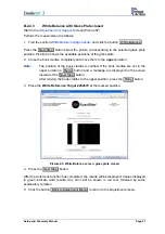
Страница 55: ...the Next Step button below the picture corresponding to the selected glass plate position 2 Close the book cradles completely and move them to the lowest position Note The position of the book cradle...

Страница 56: ...p button The measurement starts After the Autofocus function has completed the results will be displayed Values displayed in green indicate valid results Any error will be shown in red text followed b...

Страница 57: ...is verified If the book cradles are not in the upper position a Retry button and a message are displayed on the screen instead of the Next Step button After moving the book cradles to the upper positi...

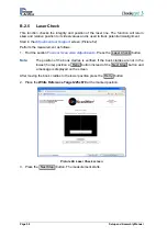
Страница 58: ...ocus Scan Area Adjustments Press the Laser Check button Note The position of the book cradles is verified If the book cradles are not in the lowest home position a Retry button instead of the Next Ste...

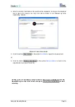
Страница 59: ...check result 5 Click the button New Values in the section Controls to repeat the measurement Or 6 Click the button Back to Adj Menu in the section Menu controls to return to the adjustments menu see P...

Страница 60: ...er optional functions B 3 1 Time Server Locate the section Base Settings in the Poweruser screen Click the button Adjust Time Date to set various parameters Picture 68 Adjust Time Date screen Select t...

Страница 61: ...loaded Picture 69 S2N Sound System screen A sound file can be assigned to various action items The assigned sound will be played every time the condition occurs The default setting can be overwritten...

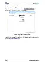
Страница 62: ...update behavior of the scanner from the list Picture 71 Update Scanner firmware screen Browse and select the previously downloaded firmware update file The appropriate firmware can be downloaded from...

Страница 63: ...n If the key text does not turn green the key is invalid or does not belong to this specific scanner or option Note Option keys are valid only for one option on a specific scanner denoted by its seria...

Страница 64: ...pdates Uploads and go to ICC Profiles Picture 73 ICC Profile screen Select either Printer Profiles or Scanner Profile In the next screen browse for a new ICC profile and select it It will replace the...

Страница 65: ...ady slowed down significantly particularly if the file sizes are large Sometimes the network s response times are poor because routers and or switches with slow performance are used or the topology of...

Страница 66: ...75 Network Analyzer Parameters screen Check the results in the following screen Single digit millisecond response times are good the example shown is from a well structured gigabit network Picture 76...

Страница 67: ...age Quality Server online 24 hours at 7 days a week The Image Quality Server can be reached at http service imageaccess de The server automatically analyzes color tracking white and black points geome...

Страница 68: ...ccess de and the system will generate an ICC profile This profile can then be uploaded into the scanner Locate the section Adjustments Support go to Scan Test Targets and click the button Scan IT8 Tes...

Страница 69: ...ry Defaults Write down the values for IP address subnet mask and gateway of the device before starting the recovery sequence The recovering to factory defaults described in the following should only b...

Страница 70: ...the factory default value 192 168 1 50 8 Change the network parameters to the values which were used before running the recovery sequence Select Setup Device Poweruser Locate the section Base Settings...

Страница 71: ...ance Go to the White Balance function and modify the Brightness Correction setting Image is darker on one side than on the other side The electronics gear is out of sync Exercise the Scan Start proced...

Страница 72: ...The scanner s optical middle in the horizontal direction is lost or misaligned Exercise the Scan Start procedure A small portion of the lower side of the target is missing in the image The scanner s o...

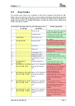
Страница 73: ...ing does not exist The settings does not exist 12 Invalid user docsize The size of the user format is invalid 14 Invalid resolution or color mode Either the resolution or the color mode is invalid 15...

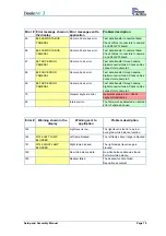
Страница 74: ...h cable is defective 30 File format not supported The specified file format is not supported or it is invalid in combination with the color mode 55 E55 WRONG S2N HW CCD PORTS Wrong S2N board detected...

Страница 75: ...nnectors to camera 2 69 E69 ADC ERROR CAMERA 3 Camera 3 adc error Test data transfer through analog digital converter failed Check cables connectors to camera 3 75 General keyboard error General keybo...

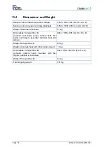
Страница 76: ...LUX Stand by 300 sec 1000 LUX Stand by idle 0 LUX lamps off Lamps High Power White LED UV and IR radiation free Lifetime 50 000 hours on time Book Cradle Maximum load book cradle plate 15 kg D 2 Ambie...

Страница 77: ...est mode 150 W Start procedure 260 W Stand by operational lamps off 105 W Stand by operational lamps on 140 W Operating 275 W Pre Scan 170 W Moving the book cradle lamps on Both plates simultaneously...

Страница 78: ...1 contains main body lamps camera neck foot pedal test targets assembly material tools and cables 490 x 1055 x 945 mm H x W x D Weight Transport Box 1 89 kg Weight of camera head with short neck elem...

Страница 79: ...Notes Setup and Assembly Manual Page 79...

Отзывы: