


31
INSTALLER
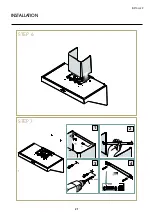
INSTALLATION
FUME EXHAUST CONNECTION
DUCTING/SUCTION VERSION
This type of hood is equipped with a top air outlet for
discharge
of fumes outside the house, which has to be connected
with the inlet of the building chimney, commonly
through a hose (not provided).
Horizontal tube sections must be slightly tilted upwards,
to help channelling of the air to the outside. Fume di-
scharge tubes crossing particularly cold environments
(e.g. attics) should be insulated, to prevent condensation
caused by temperature differences.
Suction type hoods DO NOT require carbon filters, which,
on the contrary, can limit their performance.
Any changes to the tube, sudden diameter reductions,
and bends, may prevent the hood from reaching opti-
mum suction capabilities, and may jeopardise the ope-
ration of the motor, relieving the Manufacturer from all
responsibility.
Make sure that the flue is in perfect working order, and
that a square (concrete) or round (metal) static wind
break ventilation tower with useful output section not less
than double the diameter of the flue (UNI 7129) is instal-
led at the top of the flue itself.
Comply with all air discharge regulations.
The drain chimney of the building should be
dedicated to the hood only, so under no circu-
mstances it should be shared with other devices,
such as bathroom extractors, air-conditioning
units, fireplaces, wood or gas stoves.
FILTERING/AIR RECYCLE VERSION
In order to prevent both the flow of unclean air
in the room and any damage to the fan blower,
once saturated, the carbon filters should be
promptly replaced. Once the carbon filters are
saturated, they should be replaced as soon as possible,
to prevent both the flow of unclean air and damages to
the blower fan.
external
evacuation
hood
fumes and
steam
fumes and
steam
internal air
recirculation
hoob
metal filters
metal
filters
active
carbon
filter
Содержание AGQ100
Страница 2: ......
Страница 19: ...19 INSTALLER INSTALLATION STEP 2 STEP 3 2 1 1000 MM 4023 64 min 1000 MM 4023 64 min ...
Страница 20: ...20 INSTALLATION STEP 4 STEP 5 1 2 1 ø8 mm ø 05 16 1000 MM 40 23 64 min 1000 MM 40 23 64 min ...
Страница 21: ...21 INSTALLER INSTALLATION STEP 6 STEP 7 1 3 4 2 ø8 mm ø 05 16 40 mm 137 64 ...
Страница 22: ...22 INSTALLATION STEP 7 STEP 8 ...
Страница 23: ...23 INSTALLER INSTALLATION STEP 9 STEP 10 2 1 150 mm 5 29 32 min 3 2 1 3 4 ...
Страница 24: ...24 INSTALLATION STEP 11 2 3 4 1 ø8 mm ø 05 16 40 mm 137 64 STEP 12 ...
Страница 25: ...25 INSTALLER INSTALLATION STEP 13 1 2 STEP 14 ...
Страница 26: ...26 INSTALLATION STEP 15 STEP 16 2 1 ...
Страница 32: ......


