R
u
g
e
d
M
a
c
h
in
V
is
io
n
A
va
D
ig
it
lM
C
m
ra
s
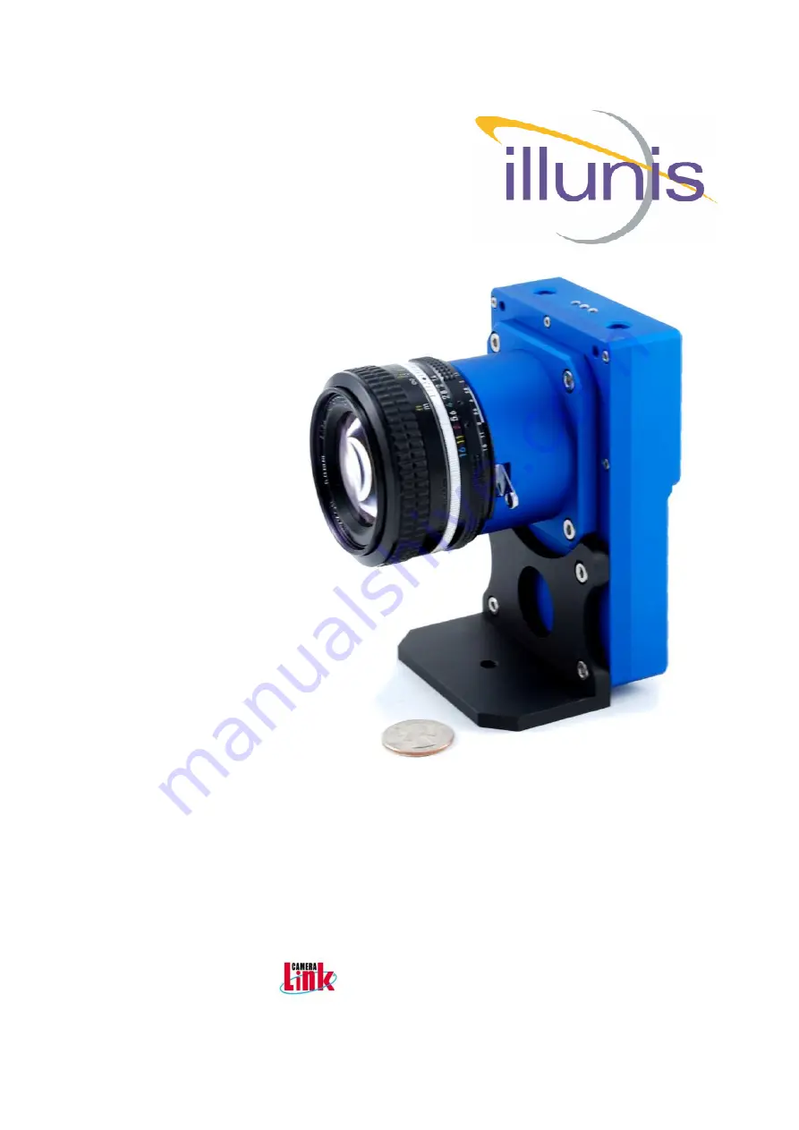
Operations Manual
RMV-71
Release 5/19/2014
All manuals and user guides at all-guides.com
all-guides.com
Страница 1: ...Rugged Machine VisionAdvanced Digital Machine Vision Cameras Operations Manual RMV 71 Release 5 19 2014 All manuals and user guides at all guides com a l l g u i d e s c o m...
Страница 2: ...est possible documentation for the RMV cameras and we will update this document with your feedback We welcome comments and criticism of this document This document covers the CMOS RMV 71 cam era link...
Страница 3: ...roducts at the industries most competitive prices As a self funded company illunis is a stable reliable source for demanding OEM s who include the most pres tigious names in the world We in vite you t...
Страница 4: ...ibration will require optical set up that involves dark and bright fields Please note that the specification for the pixel clock of the CHR 70M is 30Mhz The fundamental limitation is the maximum camer...
Страница 5: ...d if the camera is opened or modified in any way not approved by illunis Contact illunis for any questions or problems Issue Date Modification 1 11 5 13 Original Document 2 Clean up of 0x hex variable...
Страница 6: ...the following Install your capture card and software Install the illunis control program Unpack the RMV 71 install the lens Connect the RMV 71 power cable Make sure the DC ground of the power cable i...
Страница 7: ...effective frames per second The camera can be triggered from the camera link or the external power cable The camera requires dark field and bright field image calibration to eliminate sen sor column...
Страница 8: ...8 Table Of ContentsRugged Machine Vision Chapters 1 RMV 71 Overview 2 Hardware 3 Software GUI 4 Image Exposure 5 Image Processing 6 Image Detectors 7 On Screen Displays 8 Camera Link 9 Timing Tables...
Страница 9: ...iming for free run and trigger modes Mono or Bayer pattern output Sensor Specifications Full well charge 13ke Sensitivity 0 15 A W 555nm Dark Noise 7E Conversion factor 63 uv e Dynamic range 63dB Dark...
Страница 10: ...Mhz 340Mpix s Medium mode can be selected to run at manufactures specified speed of 30Mhz per tap giving a clock rate of 60Mhz and a full frame rate of 3fps Medium mode can also be selected to run at...
Страница 11: ...phase sensing phase Typically the user never has to adjust the ADC The RMV 71 FPGA reorders the tap data into two paths of pixels odd and even and outputs the pixels onto a camera link bus The output...
Страница 12: ...RMV 71 Operations Copyright illunis LLC 5 19 2014 Page 12 All manuals and user guides at all guides com...
Страница 13: ...el Clock 30 40Mhz Shutter Speed Increments of one line time Windowing H increments of 16 columns V increments of 8 rows Black Level Adjustable Analog Gain 1X 40X Digital Gain 1X 16X 1 4096 step Exposu...
Страница 14: ...g the warranty period illunis will at it s option either repair or replace the unit In the case of replacement illunis reserves the right to re use the original CCD serial number if found to be perfor...
Страница 15: ...r Consumption The RMV 71 can operate in the following modes with estimated power Base mode at 20Mhz pixel clock 4 2W 12VDC Medium mode at 30Mhz pixel clock 5 2W at 12VDC Medium mode at 40Mhz pixel clo...
Страница 16: ...is LLC 5 19 2014 Page 16 Chapter 2 HardwareRugged Machine Vision 2 0 Hardware Overview 2 1 Case 2 2 CAD Models 2 3 Cables 2 4 Considerations 2 5 Options 2 6 Optics All manuals and user guides at all g...
Страница 17: ...or replaced with alternate lens mounts The case does not incorporate a fan however at maximum power the camera will draw 6W The camera incorporates a OLED graphical display as well as LED s and two bu...
Страница 18: ...RMV 71 Operations Copyright illunis LLC 5 19 2014 Page 18 Three View All manuals and user guides at all guides com...
Страница 19: ...right illunis LLC 5 19 2014 Page 19 Top view Bottom view OLED Menu Select Button Status and Motion LED s Mode Select Button Power Connector Camera Link Base Camera Link Medium All manuals and user gui...
Страница 20: ...lunis com CAD Models supported are STEP IGES ProE native and many others 2 2 Hardware CAD Models HRS 2 3 Hardware Power Connector Pin Number Signal Type Description 1 6 to 12V DC Power DC Power in 2 D...
Страница 21: ...N 21 01429 This cable can be sourced through Components Express as PN CC C114 http www componentsexpress com A generic power cable supply is available as PN 21 01164 This can be sourced through Compon...
Страница 22: ...componentsexpress com Configurator aspx cnfi 1 The following example 5M cable configurations have been tested and are supported POCL Power Over Camera Link Base mode Standard MDR MVC 1 1 5 5M POCL MV...
Страница 23: ...tions Copyright illunis LLC 5 19 2014 Page 23 2 4 Hardware Optional Tripod Mount An optional tripod mounting brack et is available for the RMV 71 il lunis PN 26 01816 All manuals and user guides at al...
Страница 24: ...ains many advanced circuits and performs at very high clock speeds and thus requires careful consideration for thermal cooling The camera should be used either with a lens and or a solid mechanical mo...
Страница 25: ...lens using custom Copal 0 Mount Provides integrated mechanical shutter and iris Custom designed lens mount Contact illunis Sensor Options RGB Bayer with micro lens D263 AR Coated cover glass Mono with...
Страница 26: ...57mm focal length Full Frame 35mm format sensor 36x24mm CHR70M sensor 31x22mm The CMOSIS CHR70M sensor pixel size is quite small for a large sensor at 3 1um pitch This presents a challenge for the se...
Страница 27: ...accelerometer and gyroscope to measure motion This is useful for indicating that the camera is in motion and the image may be blurry The three LED s at the top of the camera flash with increasing inte...
Страница 28: ...2014 Page 28 Chapter 3 Software ICDRugged Machine Vision 3 0 Software Overview 3 1 Serial Interface 3 2 Command packets 3 3 Command Table 3 4 System Status 3 5 Baud Rate 3 6 Graphical User Interface A...
Страница 29: ...l The communication path from frame grabber to the RMV is through the Camera Link cable The Camera Link committee has specified that devices connected must first communicate at 9600 baud This default...
Страница 30: ...0x100 0xfe 0xf0 0x12 Checksum of Command and Data checksum comandindex checksum data Example4 Command 0400 data 0x0001 0x100 0x04 0x00 0xFC 0x100 0x00 0x01 0xFF Checksum lower byte of 0xFC 0xFF 0xFB E...
Страница 31: ...Window 3830x2160 in center of sensor 0x5E 0x03 Pre set Window W Window 640x480 in center of sensor 0x5E 0x04 Pre set Window W Window 7680x4320 in center of sensor 0x5E 0x05 Pre set Window W Window 25...
Страница 32: ...ble Row DC 0x04 0x24 Digital Gain R W In units of 1 4096 gain Example 0x1000 1X gain 0xC800 12 5X gain 0x04 0x30 Digital Offset R W Signed value 0x0100 offset of 256 0xFEFF offset of 255 0x04 0x38 Dig...
Страница 33: ...x04 0x17 OSD Text Window Y location R W 0x04 0x19 Show Detectors W 0x0002 AE Window 0x0003 AF Win 0x0007 AF Data 0x0009 disable 0x04 0x1a Read Detectors R 0x0002 AE Window 0x0003 AF Win 0x000a Frame C...
Страница 34: ...and Status 0x05 0x00 Camera mode status R 0x0000 read mode register 1 0x0001 read mode register 2 0x0002 read mode register 3 0x0003 read mode register 4 0x0005 read status register 1 0x0006 read stat...
Страница 35: ...0x00 Save Camera State W Wait for acknowledge before re moving power 0x03 0x02 Restore Factory State W Wait for acknowledge before re moving power 0x03 0x03 Copy User to Factory W Wait for acknowledge...
Страница 36: ...low 0x0013 Read Exposure value hi 0x0014 Read CRC 0x07 0x00 Camera Parameters R 0x0000 Camera Model 0x0001 Camera Hardware rev 0x0002 Camera Serial Number 0x0003 Micro firmware rev 0x0004 FPGA major...
Страница 37: ...de register 3 0x0003 read mode register 4 0x0005 read status register 1 0x0006 read status register 2 0x07 0x00 Camera Parameters R 0x0000 Camera Model 0x0001 Camera Hardware rev 0x0002 Camera Serial...
Страница 38: ...error V5_ERR 1 1 5V Switcher error VF_ERR 1 1 FPGA 1 2 or 2 5V Error FACT_CRC_ERR 1 1 status_register1_t typedef struct Status Register 2 unsigned int ADC_VID1_SAVE_FAIL 1 1 ADC 1 state save fail ADC_...
Страница 39: ...rrector Enabled RDC_EN 1 1 Row Defect Corrector Enabled M2_B7 1 CGT_enabled 1 CGT_LOADED 1 1 Column Gain Table Loaded from EEPROM COT_enabled 1 COT_LOADED 1 1 Column Offset Table Loaded from EEPROM M2...
Страница 40: ...et the camera must be re powered to set the rate Serial Commands Target Index Command R W Description 04 09 Set Current Baud Rate W 0x0000 9600 0x0001 19200 0x0002 38400 0x0003 57600 0x0004 115200 04...
Страница 41: ...meras illunis has provided a graphical user interface GUI The GUI is a visual program that consists of several windows menus and dialog boxes for each of the many features of the RMV camera The GUI is...
Страница 42: ...ious functions of the camera Men us are used to access sub dialogs A generic camera register read write feature is provided In addition a history of communication is also provided in this dialog box M...
Страница 43: ...ialog is used to load FPGA and Microprocessor code as well as the EEPROM configuration data Contact illunis for usage A useful feature of this dialog is the save and restore of the camera to and from...
Страница 44: ...s LLC 5 19 2014 Page 44 Chapter 4 ExposureRugged Machine Vision 4 0 Overview 4 1 Free Run Mode 4 2 Trigger Mode 4 3 Window Readout 4 4 Strobe Output 4 5 Software Trigger 4 6 Analog Control All manuals...
Страница 45: ...s of a sampling period and a readout period During the sampling period commonly call Row Overhead Time ROT the pixels are copied into the columns of the sensor Then the pixel values stored in the colu...
Страница 46: ...xposure Free Run Mode Set Exposure Time The exposure time is set In either milliseconds or microseconds The resolution of the exposure is in horizontal line times Two commands are provided for calcula...
Страница 47: ...or 0x5E 0x04 Pre set Window W Window 7680x4320 in center of sensor 0x5E 0x05 Pre set Window W Window 256x256 in center of sensor 0x5E 0x06 Pre set Window W Window 1024x1024 in center of sensor 0x5E 0x...
Страница 48: ...t be inactive when using software trigger 4 4 Exposure Strobe Signal The RMV Strobe signal is a 3 3V LVTTL signal that is active whenever the sensor is triggered and ex posing and image The strobe sig...
Страница 49: ...d by an analog front end AFE Each AFE has two gain stages and a 12bit analog to digital converter The CMOS Sensor has a additional internal gain stage This gain is normally set to minimum to re duce s...
Страница 50: ...50 Chapter 5 Image ProcessingRugged Machine Vision 5 0 Overview 5 1 Tap Output Order 5 2 Digital Gain Offset 5 3 Defect Correction 5 4 Flat Field Correction 5 5 Offset Calibration 5 6 Histogram Equal...
Страница 51: ...data cor rection of pixel column row defects and responses and video analysis tools For example the pixel pipeline of a medium format output with a 30Mhz pixel Clock is 5 1 Image Processing Tap Outpu...
Страница 52: ...ges allow for full 12 bit precision without round off error Serial Commands Target Index Command R W Description 0x04 0x24 Digital Gain R W 0x04 0x30 Digital Offset R W 0x04 0x38 DGO Enable R W 1 enab...
Страница 53: ...fect editor to simplify the editing of defect mapping Serial Commands Target Index Command R W Description 0x04 0x1c Defect Correction DC Write 0x0000 Load Enable Pixel DC 0x0001 Load Enable Column DC...
Страница 54: ...offset correction will correct the 16 column analog offsets through digital to analog convert ers The sensor also requires a digital gain for each of the 10 000 columns The col umn gain corrects non u...
Страница 55: ...umbered col umns and one for the odd numbered columns A total of 10 000 column gains are cal culated and saved in the EEPROM of the camera this may take over a minute to com plete For optimum performa...
Страница 56: ...the light source as good Then press the Run Flat Field button and the calibration will complete and the column gains will be activated in the camera but not saved to EEPROM Examine the calibration re...
Страница 57: ...ok will start the offset calibration and a on screen display will be activated to show progress A series of bar graphs will display the current offset values and relative brightness As the calibration...
Страница 58: ...he equalization Serial Commands Target Index Command R W Description 0x04 0x24 Digital Gain R W 0x04 0x30 Digital Offset R W 0x04 0x38 Master DGO Enable R W 1 enable 0 disable 0x04 0x60 Histogram EQ E...
Страница 59: ...RMV 71 Operations Copyright illunis LLC 5 19 2014 Page 59 Low contrast Image before histogram equalization Low contrast Image after histogram equalization All manuals and user guides at all guides com...
Страница 60: ...DetectorsRugged Machine Vision 6 0 Overview 6 1 Brightness 6 2 Sharpness 6 3 SNR 6 4 Raster Measurement 6 5 Temperature 6 6 Frame Counter 6 7 Bin Histogram 6 8 BIT Built In Test 6 9 Accelerometer and...
Страница 61: ...in several modes that allow the measurement of image brightness The focus detectors measure the sharpness of the image and can be used for auto focus optics In addition to the detectors the windows of...
Страница 62: ...x03 0x0c 0x13 AE Detector Data Top Register Address R W Location in units of 16 lines 0x003d Set AE Top location 0x03 0x03 0x0c 0x13 AE Detector data Right Register Address R W Location in units of 16...
Страница 63: ...w Detectors W 0x0003 AF Window 0x0007 AF Data in AF Window 0x0008 AF Data Full Screen 0x0009 disable 0x04 0x1a Read Detectors R 0x0003 AF Window Quick FAQ s The AFD window is the same as the AED win d...
Страница 64: ...71 Operations Copyright illunis LLC 5 19 2014 Page 64 6 3 Detectors SNR Detectors Coming Soon Serial Commands Target Index Command R W Description Quick FAQ s All manuals and user guides at all guides...
Страница 65: ...0003 Read Active lines per frame in FVAL 0x04 0x14 Line of Interest R W Line number from top of image Plus FVAL start Quick FAQ s LVAL Line VALid This Camera Link signal indi cates when pixel data is...
Страница 66: ...Celsius Quick FAQ s Temperature is read in degrees Celsius Temperature accuracy is 0 5 degrees 6 6 Detectors Frame Counter A Frame Counter is implemented in the RMV FPGA Each frame read has a unique c...
Страница 67: ...ount can be used easily to calculate percentages of pixel counts within the bins Serial Commands Target Index Command R W Description 0x04 0x1a Read Bin and AED size values R 0x0011 Bin 0 0x0012 Bin 1...
Страница 68: ...Returns nothing 0x99 0x02 Return 1 8V A R Voltage 10 0x99 0x03 Return 1 8V B R Voltage 10 0x99 0x04 Return 5V R Voltage 10 0x99 0x05 Return 3V R Voltage 10 0x99 0x06 Return 2 5V R Voltage 10 0x99 0x0...
Страница 69: ...var 0x57 0x03 Read Y axis R Reads internal var 0x57 0x04 Read Z axis R Reads internal var 0x57 0x05 Read sum of all axis change from last reading R 0x58 0x00 Initialize Gyroscope R 0x58 0x01 Read Gyr...
Страница 70: ...rations Copyright illunis LLC 5 19 2014 Page 70 6 10 Detectors Light Meter Coming soon Serial Commands Target Index Command R W Description Quick FAQ s IComing Soon All manuals and user guides at all...
Страница 71: ...ge 71 Chapter 7 OSDisplaysRugged Machine Vision 7 0 Overview 7 1 Text 7 2 Line Plot 7 3 Column Plot 7 4 Cross Hair 7 5 Synthetic Patterns 7 6 Detector Display 7 7 Histogram 7 8 OLED All manuals and us...
Страница 72: ...ntal line plot or Vertical column plot display Display of the image histogram as a line plot or a bar graph Selectable line column of interest for display Selectable baseline position for the plot dat...
Страница 73: ...n To access one of the 128 character memories as 16 lines of data per character the OSD address is formatted as a 16 bit word To access one of the screen memory locations 128 columns and 32 lines the...
Страница 74: ...S Text Window X location R W Increments of 128 pixels 0x04 0x17 OSD Text Window Y location R W Increments of 64 lines 0x12 Char Font pattern W Custom Font Entry 0x13 Char Data HHVV W HH horizontal byt...
Страница 75: ...s well as some special characters If you write an application to display all character values from 0 to 127 you can see the entire character set as seen in the image below Horizontal Index This regist...
Страница 76: ...awn on a 4Kx4K image Only the first 4096 data points of a line may be displayed lines longer that 4096 will wrap Serial Commands Target Index Command R W Description 0x04 0x11 OSD lines W 0x0000 disab...
Страница 77: ...w as line 0x0009 draw as filled 0x04 0x12 Line Plot Offset R W 0x04 0x13 Line Plot Scale R W 0x04 0x14 Line Plot Line of Interest R W Quick FAQ s The column plot display is one frame behind it s measu...
Страница 78: ...s Serial Commands Target Index Command R W Description 0x04 0x06 Test Pattern W 0x0000 Normal Video 0x0001 Input CCD Test Pattern 0x0002 Output Test Pattern Quick FAQ s The input test pattern can be u...
Страница 79: ...erlay on the image for reference Serial Commands Target Index Command R W Description 0x04 0x19 Show Detectors W 0x0002 AE Window 0x0003 AF Window 0x0007 AF data 0x0008 AF data window screen 0x0009 di...
Страница 80: ...stogram zoom function Serial Commands Target Index Command R W Description 0x04 0x11 OSD histogram line plot W 0x0000 Disable plots 0x000C Enable Histogram display 0x000D Histogram Zoom low 512 0x000E...
Страница 81: ...9 2014 Page 81 Chapter 8 Camera LinkRugged Machine Vision 8 0 Overview 8 1 Pixel Format 8 2 Channel Format 8 3 FVAL LVAL 8 4 Raster Detectors 8 5 Capture Card Setup 8 6 POCL All manuals and user guide...
Страница 82: ...ectors 0x0003 AFE 0x0004 Built In Test 0x0006 Accel and Gyro 0x0007 Off 0x5F 0x01 Put character W Char 0x5F 0x02 Clear screen W 0x5F 0x03 Move cursor W 0xHHVV 0x5F 0x04 Text Foreground color W 0x5F 0x...
Страница 83: ...a to capture circuit Image data and image enables are transmitted on the Camera Link bus The four Enable signals are FVAL Frame Valid is defined HIGH for valid lines LVAL Line Valid is defined HIGH fo...
Страница 84: ...it Width W 0x0000 12 bit mode 0x0001 10 bit mode 0x0002 8 bit mode 0x0003 Bottom 8 bits as Msb Quick FAQ s Bottom 8 is very useful for evaluating camera noise Sensors rated at 60dB SNR have about 10 c...
Страница 85: ...mode requires two camera link cables and a capture card Serial Commands Target Index Command R W Description 0x04 0x00 CL Format W 0x0000 Camera link Base 0x0001 Camera link Medium 0x0002 Camera link...
Страница 86: ...s are not stored on system save and must be reprogrammed each time they are Serial Commands Target Index Command R W Description 0x04 0x1b System Registers R 0x0008 LVAL Start 0x0009 LVAL Stop 0x000a...
Страница 87: ...ed in the built in test functions of the camera Serial Commands Target Index Command R W Description 0x04 0x1b System Registers R 0x0000 Pixels per line 0x0001 Active pixels per line 0x0002 Lines per...
Страница 88: ...mExpert Setup Xcelera CL_PX4 Example Medium format 4 pixels per clock Left to right Top to bottom Note changing from Top to bottom to Bottom to top will flip the image vertically Base format 2 pixels...
Страница 89: ...Copyright illunis LLC 5 19 2014 Page 89 8 5 Camera Link Matrox intellicam Setup Base format 2 pixels per clock Left to right Medium format 4 pixels per clock Left to right All manuals and user guides...
Страница 90: ...71 is designed to the POCL specification Due to certain timing and power restrictions the POCL interface is not currently available POCL PWR Note Internal PC power may be required to power the camera...
Страница 91: ...RMV 71 Operations Copyright illunis LLC 5 19 2014 Page 91 All manuals and user guides at all guides com a l l g u i d e s c o m...
Страница 92: ...o 6 Connector Strobe Out 12V DC In Camera Link Connector 5 Pairs of video data 4 data and 1 clock 2 Pairs of com data Send and Receive 4 pairs of camera control CC1 CC2 CC3 CC4 Where CC1 trigger Lens...
Страница 93: ...unis LLC 5 19 2014 Page 93 FAQRugged Machine Vision This section of Frequently Asked Questions is intended to help the first time user to setup and control the camera FAQ 1 Coming soon All manuals and...
Страница 94: ...whose failure to perform can be reasonably expected to cause the failure of the life support device or system or to affect its safety or effectiveness illunis assumes no liability for applications as...
Страница 95: ...13 First release of demo systems F0 40 1 15 14 Addition of individual column offsets in addition to internal 16 column offset registers Improvement of FFC and black level setting F0 41 3 7 14 Producti...