1
03- RECEIVER’s INSTALLATION
03- RECEIVER INSTALLATION
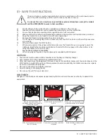
WARNING
Manage the complete shut down of the machine throughout the whole installati on of
the receiver, following the legislati on on occupati onal risk presenti on in force.
Check the power supply and shut down the main switch, disconnecti ng the interface
cable between the receiver and the machine’s electrical box.
Remember that the receiver has more than one circuit of low tension. Even if the power
supply of the receiver is not connected, there is sti ll risk of electric shock.
HOW TO LOCATE THE RECEIVER
2
3
1. Find a easily accesible and clear locati on, if possible with a direct vision between the receiver’s antenna and
the transmitt er’s working area.
2. In case it is diffi cult to achieve a direct vision between the receiver’s antenna and the transmitt er’s working
area, it is recommended the use of an extern antenna and the locati on of this antenna in clear areas with the
antenna extension (in those models that allow an antenna).
In areas where there’s expected a high vibrati on level of the machine, the use of dampers is adviced.
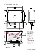
3. Proceed the connecti on of the power supply and the receiver’s outputs. Use the connecti on block diagram
provided with the system, where it is detailed the correspondence between the transmitt er maneuvres and
the receiver’s outputs.
4. Check the electrical installarion and verify if there’s an opti on to connect the neutral or the ground cable. In
that case, don’t forget to connect the ground cable.
The use of fi reproof or fl ame retardant cables is recommended for the connecti on.
04- TROUBLESHOOTING
04- TROUBLESHOOTING
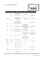
LED
COLOUR
CONDITIONS
REMARKS
PROPOSED ACTION
POWER
GREEN
Switch ON if powered.
Power supply OK.
Check the power supply.
HARDOK
GREEN
Solid green LED if no error
detected
Receiver hardware OK
OK
Blinking during start up process
Please wait to finish the start-
up process
RED
If there’s an error of:
-
Watchdog activated / oscillator
stopped / wrong EEPROM
checksum
-
Reset activated.
Electronic board hardware
breakdown
Replace electronic board
-Blinking if checksum EEPROM
error/ Data corrupted / bus CAN
error detected-> CAN-ERR
----------------
Reprogram EEPROM
SIGNAL
GREEN
LED Off if no radio signal detected
(Squelch).
- LED On and the transmitter
switched Off indicates
occupied radio channel
- LED On and DATA switched
Off indicates radio channel
occupied by a non IKUSI
system
Change Transmitters
Frequency Channel
DATA
GREEN
Switch off if the received frame
has an error
Blinking if receiving good frames
Switch off and LED SIGNAL
switched on: Radio error
Replace radio
ID
GREEN
Blinking if a correct ID is received
Switched Off and DATA LED
switched On: no valid ID (ikusi
system nearby)
If channel not occupied: Check
chosen ID in the transmitter or
reset the receiver.
SIGNAL; DATA and ID LED On,
indicates valid frames from
the transmitter. Correct link.
OK
RELAY
GREEN
STOP relay activated
----------------
----------------
ORDER
GREEN
----------------
----------------
----------------
CAN_RUN
GREEN
-Switched on: operational state
-Blinking: Pre-operational state
OK
----------------
----------------
----------------
CAN_ERR
RED
-Switched on: BUS CAN error
-Blinking: No BUS connection
-Switched off: Correct
communication
----------------
Blinking
----------------
Check CAN Connection
Check bus termination
resistance
----------------
ORDER
REL
AY
ID
DA
TA
SIGNAL
HARDO
K
POWE
R
CANRUN*
CANERR*


