background image

55

SSW

WIITTCCH

HEESS // FFIILLM

M GGAAU

UGGEE

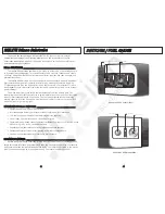
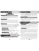
The DS200 features separate switches for power on/off and firing modes. The line

thru the switch points to the selected position.

O

ON

N//O

OFFFF SSW

WIITTCCH

H ________________________________________________________________________________________________________

O

OFFFF:: The upright switch position is OFF. The adjacent tab locks the switch in the

OFF position. To unlock, move the tab away from the switch. Always turn the Substrobe

OFF before opening the battery compartment.

O

ON

N:: There are two ON positions. The first ON position turns on the power to the

Substrobe. The second ON position turns on both the power to the Substrobe and the

modeling light.

BBAATTTT:: Occasionally check the battery capacity by rotating the switch to the BATT

position and referencing the fuel gauge on the opposite side of the strobe. The BATT position

also turns ON the modeling light as a reminder that the switch is in the BATT position.

FFU

UEELL GGAAU

UGGEE________________________________________________________________________________________________________________

When the switch is rotated to the BATT position, the fuel gauge on the Opposite

side of the strobe will display 0, 1, 2, or 3 red LED lights indicating the remaining charge

in the battery pack (see below). A fully charged NiMH pack will provide at least 160 full

power flashes and all 3 LED's should light. When no LED's are illuminated, then the

battery capacity is low and you may have less than 36 full power flashes remaining. For

general guidelines, refer to the following list:

• 3 LED’s - above 75%
• 2 LED’s - above 50%
• 1 LED - above 25%
• No LED - less then 25%

FFIIRRIIN

NGG M

MO

OD

DEE SSW

WIITTCCH

H______________________________________________________________________________________________

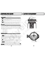
Multiple firing modes are featured: TTL/Auto and four manual power settings:

Full, 1/2, 1/4, and 1/8.

TTTTLL//AAuuttoo - 

Thru-The-Lens/Auto Exposure: The camera automatically signals the

strobe to turn off when the exposure is correct. The camera must feature compatible

TTL/Auto exposure to utilize this mode on the DS200 when connected directly to the

camera. (See “Compatible Cameras” and “TTL/Auto Exposure” sections). The TTL/Auto

firing mode MUST be selected when connecting the optional DS Sensor #4100.5 or

EV-Controller #4100.6.

FFuullll - 

Full Power Manual Exposure: The strobe fires at full power each time. You

must select the correct exposure manually. Set the camera aperture based on the subject

distance (see "Exposure Guide" section).

11//22,, 11//44,, 11//88 - 

Manual Exposure Modes: Select the appropriate power setting to

manually balance the strobe output for available light. Select 1/2, 1/4, or 1/8 power

when the strobe-to-subject distance is fixed and the manual full power setting would

over-expose with the camera aperture you have selected. The difference between eeaacchh

ppoow

weerr sseettttiinngg is one full f-stop; moving from Full power to 1/2 power decreases the light

output by one full f–stop. Changing the power setting does not alter the coverage angle.

66

BBAATTTTEERRYY CCO

OM

MPPAARRTTM

MEEN

NTT

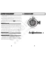
Battery Compartment

Battery Compartment

Electrical contacts

Bulb holder stem, unscrew to remove.

IK

E

L

IT

E

BA

TT


ON 

O

FF


O

1/8 

1/4


1/2


TTL 

o'ring

battery compartment door

S

u

bs

tr

ob

e

20

0

Содержание DS-200

Страница 1: ...mm SLR with diffuser G Gu ui id de e N Nu um mb be er r I IS SO O 1 10 00 0 f fe ee et t 76 surface 38 underwater G Gu ui id de e N Nu um mb be er r I IS SO O 1 10 00 0 m me et te er rs s 24 surface 12 underwater F Fi ir ri in ng g M Mo od de es s TTL Auto Manual 1 2 M 1 4 M 1 8 M Slave featuring auto exposure using optional DS Sensor 4100 5 Slave featuring 10 manual power settings using optional ...

Страница 2: ... capacity Aim the DS200 and illuminate your subject s colors with the built in modeling light night diving light O OV VE ER RV VI IE EW W O OF F D DS S2 20 00 0 F FE EA AT TU UR RE ES S _ __ __ __ __ __ __ __ __ __ __ __ __ __ __ __ __ __ __ __ __ __ __ __ __ __ __ __ __ __ __ __ __ __ __ __ __ _ Separate power and firing mode switches Interchangeable battery pack features industrial grade NiMH ba...

Страница 3: ...maining For general guidelines refer to the following list 3 LED s above 75 2 LED s above 50 1 LED above 25 No LED less then 25 F FI IR RI IN NG G M MO OD DE E S SW WI IT TC CH H_ __ __ __ __ __ __ __ __ __ __ __ __ __ __ __ __ __ __ __ __ __ __ __ __ __ __ __ __ __ __ __ __ __ __ __ __ __ __ __ __ __ __ __ __ __ __ _ Multiple firing modes are featured TTL Auto and four manual power settings Full ...

Страница 4: ...screwdriver counter clockwise 90 and then lift off external section of the door Reverse the procedure to resecure the two battery door sections Keep o ring and sealing surfaces clean LIGHTLY LUBRICATE the o ring with the silicone lubricant provided Also lightly lubricate o ring sealing surface on the inside of the strobe body Use only enough lubricant to lightly cover the o ring wipe off any exces...

Страница 5: ...HE E S ST TR RO OB BE E _ __ __ __ __ __ __ __ __ __ __ __ __ __ __ __ __ __ __ __ __ __ __ __ __ __ __ __ __ __ __ __ __ __ __ __ __ __ __ __ __ __ __ __ __ __ __ __ _ Use the modeling light to aim the strobe Look thru the camera s viewfinder and aim the strobe so that the modeling light shines in the center of your picture area If your subject distance greatly changes you should recheck the posi...

Страница 6: ...ash compatible and provides optimum performance with traditional film cameras digital still cameras and dSLR cameras in related Ikelite housings The DS200 strobe is compatible for eTTL and iTTL with the Ikelite housing system The appropriate sync cord or sensor must be connected to trigger the DS200 strobe The TTL Auto exposure mode on the Ikelite DS200 strobe is compatible with the following TTL ...

Страница 7: ... Auto exposure signal from the camera to the strobe Please review the Compatible Camera section on the previous page for additional information T TT TL L S SY YN NC C C CO OR RD DS S _ __ __ __ __ __ __ __ __ __ __ __ __ __ __ __ __ __ __ __ __ __ __ __ __ __ __ __ __ __ __ __ __ __ __ __ __ __ __ __ __ __ __ __ __ __ __ __ __ __ __ __ _ Ikelite offers interchangeable sync cords so that different ...

Страница 8: ...rd ends are identical either end can be connected to the strobe 3 Hand tighten the knurled retaining ring on the cord Push the connector body further into the bulkhead connector and continue to tighten the knurled ring L LU UB BR RI IC CA AN NT T Use only Ikelite brand silicone lubricant with Ikelite brand o rings as other brand lubricants can cause the Ikelite o rings to swell in size D DO O N NO...

Страница 9: ...SLR cameras do not offer TTL compatible circuitry so only manual exposure is offered for the Ikelite Substrobes Select the non TTL Nikonos cord 4104 31 or 4104 32 for compatibility when connecting to the Nikonos style female socket on the non Ikelite housing Follow the procedure referenced above to connect the Nikonos cord to the housing 1 18 8 E EX XP PO OS SU UR RE E G GU UI ID DE E The purpose ...

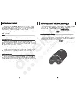
Страница 10: ... f 11 meaning you can shoot subjects up to 1m 3 6 away Substrobe 200 Front Protruding Ear Holes for Lanyard Cut out Flash Diffuser Flash Tube Tab Modeling Light 2 20 0 M MO OU UN NT TI IN NG G T TH HE E S ST TR RO OB BE E I IK KE EL LI IT TE E A AR RM M S SY YS ST TE EM MS S _ __ __ __ __ __ __ __ __ __ __ __ __ __ __ __ __ __ __ __ __ __ __ __ __ __ __ __ __ __ __ __ __ __ __ __ __ __ __ __ __ __...

Страница 11: ...the receptor Release the button and it should spring back to the original position locking the arm in place An optional longer stem 9577 33 can be purchased separately to replace the original short stem on the Digital Arm if a convenient mounting location is needed to secure the optional Ikelite DS Sensor or EV Controller T Tr ra ay y M Mo ou un nt t The Ikelite tray mount is provided with the arm...

Страница 12: ...exposure is preferred choose the optional Ikelite EV Controller 4100 6 which provides 10 manual power settings in half stop increments The EV Controller can be triggered using the built in slave sensor or an optional sync cord can be connected Always carry spare batteries Weak batteries cause many camera and strobe problems Prolong the battery life by recharging the NiMH monthly even when not used...

Страница 13: ... other photographic equipment In addition to normal procedures we strongly recommend that this strobe be returned to Ikelite periodically to be checked and pressure tested 1 We suggest storage of your Substrobe with the battery door removed to allow any hydrogen air mixture to escape 2 Always rinse the exterior of the Substrobe with fresh water after use The strobe can be cleaned by soaking it in ...

Страница 14: ...ncluding but not limited to bulb failure are not covered Except as mentioned above no other warranty expressed or implied applies to this Ikelite product We recommend adding an ALL RISK floater to your homeowner s insurance policy in the event you damage flood or lose your camera or strobe Ikelite warranty does NOT cover customer neglect R RE ET TU UR RN NI IN NG G P PR RO OD DU UC CT TS S F FO OR...

Отзывы: