Astria.us.com
126753-01M
20
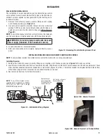
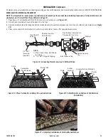
WIRING DIAGRAM
DO NOT
CONNECT
TO 120V
REPLACE FACTORY WIRING WITH 105°C
EQUIVALENT OR HIGHER RATING
THERMOSTAT WIRE 18 GA. RED/WHITE
EXTERNAL WIRING USE ONLY CLASS 2
(VENT SAFETY
SHUTOFF SWITCH)
N.C.SW
WALL SWITCH
(NOT SUPPLIED)
MANUAL
DAMPER
SWITCH
RED
WHITE
TH
TH/TP
TP
N.O. SW
O
F F
PI
LO
T
ON
PILOT SAFETY WIRE
PILOT BURNER
PILOT GAS LINE
THERMOPILE
IGNITOR
INCOMING
MAIN GAS
SUPPLY
Figure 40 - Wiring Diagram
MANUALLY-RESET SAFETY LIMIT SWITCH
This appliance is equipped with a manually-reset blocked flue safety
limit switch. Refer to
Figure 41
for its location. If, during appliance
operation, the flame goes out (independently of the burner on/off wall
switch), it may be due to the operation of this safety limit switch.
First
allow the appliance to cool
, then reset the safety switch by pressing
the red reset button on the back of the switch.
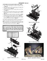
To access the blocked flue safety limit switch, refer to
Figure 41
:
1. To access the blocked flue safety switch, remove the two (2)
phillips head screws
(shown in
Figure 41
)
and pull out switch.
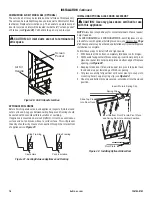
2. Press the red reset button on the switch
(see
Figure 42)
.
.
3. Reinstall switch.
The appliance should then relight and remain lit. If this does not oc-
cur,
turn off the appliance and call a qualified service technician
.
Figure 41 - Blocked Flue Safety Switch, Removal and Reinstallation
Figure 42- Blocked Flue Safety Switch, Red Reset Button
Blocked Flue Safety
Limit Switch
Red Reset Button
Blocked Flue Safety
Limit Switch
Use Phillips Head Tool

