3 – 4
MAINTENANCE
3-3 WHEN REQUIRED MAINTENANCE AND CHECKS
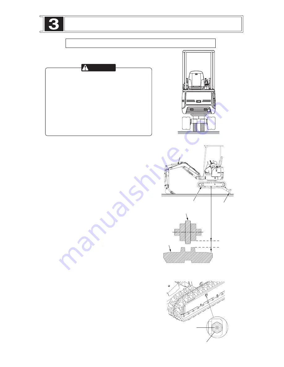
TRACKS CHECK / ADJUST
* Grease is under high pressure.
*
NEVER
remove the grease fitting.
* Grease coming out of the check valve under
pressure can penetrate the body causing
injury or death.
*
DO NOT
watch the check valve to see if
grease is escaping. Watch the track or track
adjustment cylinder to see if the track is being
loosened.
* Loosen the check valve one turn only.
Measuring Track Tension
1. Position bucket to the sprocket side. Use boom
and blade down pressure to lift the track on both
side off the ground.
2. Measure the maximum amount of the track sag
from the shoe upper face to the roller face.
Properly adjusted track will have approximately
10 to 20 mm slack with rubber shoes. In case of
steel shoes, approximately 30 to 50 mm.
Track Tightening
1. Add grease through check valve fitting
c
until
the correct track tension is reached.
2. Move the tracks forward and reverse to equalize
the pressure.
3. Check the the amount of track sag again and
adjust as necessary.
Track Loosening
1. Remove soil deposited on front idler bearing.
2. Loosen the check valve
d
carefully (one turn
maximum) until the track begins to loosen.
3. Tighten the check valve
d
to 59 to 69 N • m (6 to
7 kgf • m) when the desired track tension is
reached.
NEVER
over tighten the check valve.
4. Move the tracks forward and reverse.
5. Check the the amount of track sag again and
adjust as necessary.
If the correct adjustment cannot be obtained, consult
your IHI dealer.
W
A
R
NING
WHEN REQUIRED
G
rease
nipple
C
heck valve
(Width across flat: 24 mm)
B
oom
Sprock
e
t
Bl
ad
e
T
rack
sa
g
Sho
e
L
o
we
r
ro
lle
r
Ru
bbe
r
sho
e
s
:
10
to
20
mm
St
eel
sho
e
s
: 3
0
to
50
mm
Suport
e
d
th
e
mach
i
n
e


