Initial Operation and User Interface
37/121
Operating Manual dryve D1, ST-, DC-, EC/BLDC-Motor Control System - V2.4
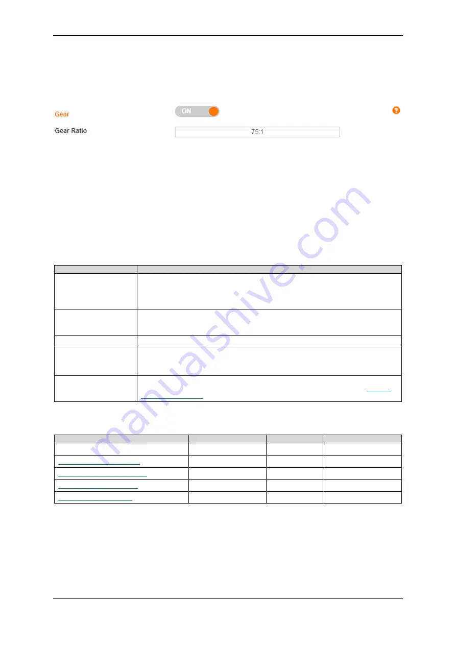
5.4.3 Gear
For igus
®
motors with motor-mounted gearboxes, all the necessary configurations have already been set.
If you have selected a "Custom article" at "Article Number" or if you want to use a gearbox that matches an igus
®
motor, please
configure the gearbox manually. For this purpose, use the Help information provided in the manual or on the user interface.
1.
Deactivate the dryve D1 by revoking the DI 7 "Enable" signal (external signal or switch on the "Inputs/Outputs" page)
6.
Activate the gearbox by setting the switch to "ON"
7.
Insert the gear transmission ratio in the "Gear Ratio" field. Please obtain the necessary information from the gearbox
data sheet
5.4.4 Feedback
With a feedback sensor, a position change during a movement can be measured. As a result, it is possible to increase
positioning accuracy and compensate for incorrect positioning (step loss). Motor-mounted encoder have already been
configured for igus
®
motors. If an axis-mounted feedback sensor or a user-defined motor with a feedback sensor is used, please
configure it manually.
Feedback
Description
Encoder as line driver
If a line driver is used, differential data transmission of the angular encoder signals is used. As
a result, the signals are considerably more resistant to interference.
Data transfer takes place on channels A, A/, B and B/. As an option, an index signal can be
transmitted via N and N/. The index signal is emitted once per motor revolution.
Encoder as single ended
If a single ended encoder is used, the signals of the angular encoder are transmitted along
channels A and B. As an option, an index signal can be transmitted via N. The index signal is
output once per motor revolution.
Hall 2-pole
The signals of 2 Hall Sensors are evaluated for position monitoring.
Hall 3-pole
The signals of 3 Hall Sensors are evaluated for commutation. They are located at 120° from
each other. To operate an EC/BLDC-Motor, the 3 Hall Sensors must be connected.
The Hall Sensors are activated automatically an
d can’t be selected separately.
Analogue feedback
If analogue feedback is used, the position is monitored by analogue position feedback sensor
connected to AI2. Carry out the further steps and then follow the instructions under
The following configurations are available
Feedback
Stepper Motor
DC-Motor
EC/BLDC-Motor
Without Feedback
Yes
Yes
Yes*
Encoder as Line Driver (p.96f)
Yes
Yes
Yes
Encoder as Single Ended (p.96f)
Yes
Yes
Yes
Not supported
Yes
Not supported
Not supported
Yes
Not supported
*The Hall 3-pole Sensor will be activated as soon as an EC/BLDC motor is selected


