Initial Operation and User Interface
73/121
Operating Manual dryve D1, ST-, DC-, EC/BLDC-Motor Control System - V2.4
5.11 Absolute Feedback
Analogue Setpoints Configuration (APS, ARO, ADR)
1.
Enter the voltage for the minimum stroke in "AI 1 Stroke Min".
2.
Enter the voltage for maximum stroke in "AI 1 Stroke Max".
Absolute Feedback Configuration
1.
Activate the
“Feedback” on the "Motor" page
2.
Select "Analogue Feedback" in the drop-down menu
3.
Select the "AAF" method (Analogue Absolute Feedback) at "Homing" on the "Axis" page
4.
Set the
DI 7 “Enable” signal (external signal or switch on the "Inputs/Outputs" page)
5.
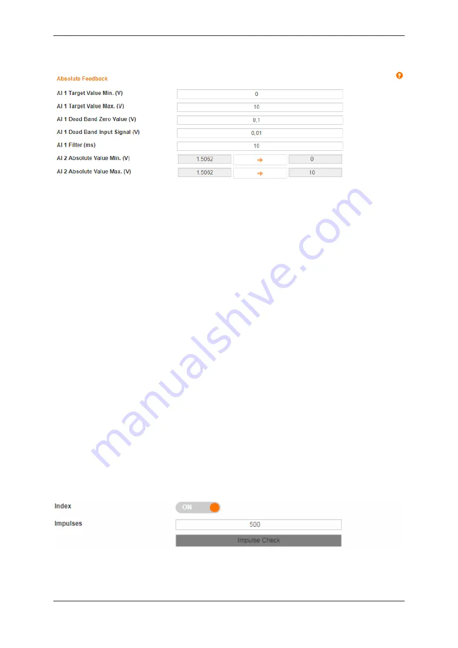
Go to the "Drive Profile" page and use the "Position Adoption" buttons to move to the negative end of the axis or to
the maximum negative position corresponding to your application
6.
Go to
“Absolute Feedback" on the "Axis" page
7.
Click on the orange arrow next to "AI 2 Absolute Value min. (V)" to automatically transfer the actual voltage value to
the field on the right
8.
Go back to the "Drive Profile" page
9.
Use the "Position Adoption" buttons to move to the positive end of the axis or to the maximum positive position
corresponding to your application
10. Go back to
“Analogue Feedback”
11. Click on the orange arrow next to "AI 2 Absolute Value max. (V)" to automatically transfer the actual voltage value to
the field on the right
The
“Absolute Feedback” has now been configured and is ready for use.
5.12 Impulse check
If you use a user-defined motor with a encoder including an index and the impulse count per motor revolution is not known, a
“Impulse Check” can be executed to determine the value.
When using the
“Impulse Check”, a distinction must be made as to whether the motor has already been installed and therefore
a physical limitation is present or whether the motor can rotate without limitation.


