


6
4
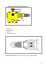
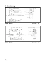
Installation
Installation must be carried out by authorized personnel. The safety rope emergency
stop switch is mounted using four M5 screws. The tightening torque for the fixing
screws is 4 Nm The tightening torque for the cover screws, the cable glands and cable
seals are 1.5 Nm to ensure protection rating IP 67. Only use seals of the correct size
for the cable entry and the external diameter of the cable.
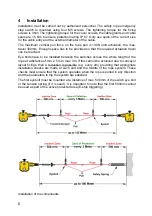
The maximum vertical pull force on the rope pull is 130N until activation, the max.
travel 300mm. Enough space has to be provided so that the required actuation travel
can be reached.
Eye bolts have to be installed between the switches across the whole length of the
rope at a distance of min. 2.5m to max. 3m. If this cannot be achieved due to conveyor
layout fixings, then a reduction is possible (e.g. every 2m) providing that appropriate
installation checks are made at each end and the middle of the rope system. These
checks must ensure that the system operates when the rope is pulled in any direction
and the parameters to trip the system are satisfied.
The first eyebolt must be mounted at a distance of max. 500mm of the switch eye bolt
or the tension spring (if it is used). It is important to note that the first 500mm cannot
be used as part of the active protected area (E-stop triggering).
Installation of the components


