IFM Electronic Ecomat 300 AL1010 Скачать руководство пользователя страница 34

IO-Link master

34

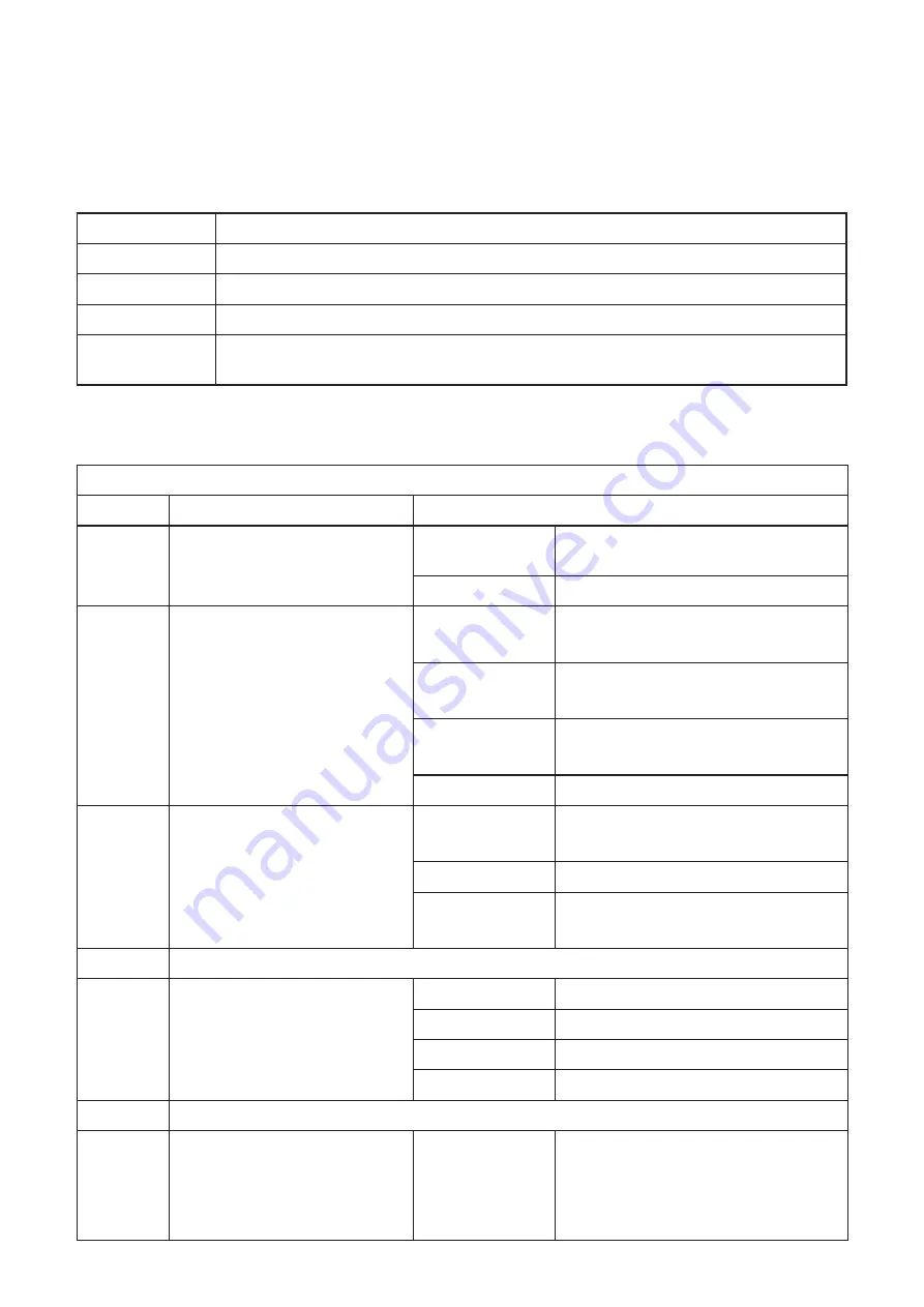
18.3  Parameter telegram

This section provides a detailed description of the format of the device parameters� 

This may be useful when setting parameters using acyclic services or if there is no 

user interface for the simple selection of parameters�

Byte

Meaning

1 … 7

DP standard

8 … 10

DP/V1 standard

11 ��� 28

Module parameter of the status/control module

29 … 237

Module parameters of the IO-Link ports 

The set-up depends on the type and sequence of the submodules inserted�

Module parameter

Module parameter "status/control"

Byte

Meaning

Contents

11

Port synchronisation

Bit 0

Free (ongoing) 

0 = deactivated; 1 = activated

Other

Reserved

12

General diagnostic settings

Bit 0

Channel-related diagnostics

0 = deactivated 1 = activated

Bit 1

Status messages

0 = deactivated 1 = activated

Bit 2

IO-Link master status diagnostics

0 = deactivated 1 = activated

Other

Reserved

13

Port specific diagnostic settings

Bit 0

IO-Link device diagnostics port 1

0 = deactivated 1 = activated

���

���

Bit 7

IO-Link device diagnostics port 8

0 = deactivated 1 = activated

14

Reserved

15

Substitute value behaviour for 

the IO-Link ports in DO mode 

(pin 4)

00

hex

Clear all

01

hex

Set all

02

hex

Hold last value

03

hex

Switch replacement value

16���17

Reserved

18

Specification of a replacement 

value sample for the 

IO-Link ports in the DO 

operating mode (pin 4)

00

hex

���FF

hex

In order to use this parameter, the 

value "Replacement values" must be 

set beforehand in the "Behavior in 

the event of error for status/control 

module" parameter�

Содержание Ecomat 300 AL1010

Страница 1: ...Device manual IO Link Profibus master AL1010 7391036 00 10 2016 UK ...

Страница 2: ...rain 10 9 2 Sources of interference 10 9 3 Cable routing in control cabinets 10 9 4 Cable routing in buildings 10 9 5 Cable routing outside buildings 11 9 6 Installing network bus cables between buildings 11 9 6 1 Causes of surge voltages 11 9 6 2 Equipotential bonding line 11 9 6 3 Surge protective devices 11 9 7 Surge protection measures 12 9 8 Grounding concept 12 9 9 Installation instructions ...

Страница 3: ...18 1 Status control module 28 18 2 Flexible module configuration 30 18 3 Parameter telegram 34 19 I M functions 37 20 Sync freeze mode 39 21 Diagnostic alarms 39 22 IO Link master 40 23 Substitute value behaviour 41 24 Setup as per STEP 7 41 24 1 Description of the setup of the device on a SIMATIC S7 controller 41 25 System requirements 41 25 1 Software 41 25 2 Hardware 41 26 Integrate ifm Profibu...

Страница 4: ...device Read this document before use to familiarise yourself with operating conditions installation and operation Keep this document during the entire duration of use of the device Adhere to the safety instructions Symbols Instructions Reaction result Designation of keys buttons or indications Cross reference Important note Non compliance may result in malfunction or interference Information Suppl...

Страница 5: ...t be connected to the protective earth PE or to the potential equalisation The system installer is responsible for implementing this connection Connection cables and signal lines must be installed in such a manner that inductive and capacitive interference do not impair the automation functions Install automation equipment and related operating elements in such a way that they are protected agains...

Страница 6: ...nd national work safety regulations have to be observed All shrouds and doors must be kept closed during operation 3 Documentation This documentation relates to the hardware and firmware status at the time of editing this manual The features of the devices are continuously developed further and improved 4 Functions and features The devices have been designed for use in applications described in th...

Страница 7: ... operated in the following operating modes DI behaves like a digital input supplied via US DO behaves like a digital output supplied via US IO Link IOL sensor supplied via US IOL actuator supplied via US and UA 5 3 Connections The bus I O devices and supply are connected via M12 screw connections Each device is connected directly to the network bus system 5 4 Protection rating The devices have IP6...

Страница 8: ...onnections for the supply voltages 4 Connections for inputs outputs or IO Link ports 5 Markers for labelling 6 Status indicators of the inputs outputs or the IO Link ports 7 Diagnostics and status indication for the supply voltages 8 Rotary coding switch no function for ProfiNet 9 Diagnostics and status indicators for the network bus system 10 Diagnostics and status indicators for the net work not...

Страница 9: ... the IO Link port If the yellow status indicators are on this indicates signal state 1 of the input output signal The devices have three main areas for diagnostics and status indicators Indicators for the network bus system network bus specific Data Indicators for the power supplies Power Indicators for the inputs and outputs and the IO Link ports device specific Signal Data Power Signal 9 Install...

Страница 10: ...Observe the specifications of the cables used 9 2 Sources of interference Signal cables and power supply lines should not be installed in parallel If necessary metal isolating segments should be placed between the power supply lines and signal cables Only use connectors with metal housing and connect as much of the shielding as possible to the housing For outdoor cables between buildings make sure...

Страница 11: ...ng network bus cables between buildings 9 6 1 Causes of surge voltages Surge voltages occur as a result of switching operations electrostatic discharge and lightning discharge Surge voltages can be inductively capacitively or galvanically coupled into electrical cables for mains supply measured value transmission and data transmission In this way surge voltages reach the power supply units and the...

Страница 12: ...ed by approximately 1 ms Relay coil with RC element For the dimensioning of the RC element the following values are recommended R 100 200 Ω C 220 470 nF 9 8 Grounding concept The devices operate in the low level signal voltage range In the case of low level signal devices interference is discharged via functional earth FE Functional earth FE is only used to discharge interference It does not provi...

Страница 13: ...on using mounting screws in order to ensure immunity to interference To ensure IP65 IP67 protection cover unused connections with protective caps Only supply the sensors with the voltage US which is provided at the terminal points Avoid polarity reversal of supply voltages US and UA Data corruption or loss Implement the FE connection using mounting screws in order to ensure immunity to interferenc...

Страница 14: ...screws with toothed lock washer and self locking nuts Observe the maximum torque of the screws Functional grounding Functional grounding is crucial for interference free operation Ground the device by means of the mounting screws of the fixing clips ...

Страница 15: ...for setting the address and if required the transmission speed see user manual for the respective network bus system The rotary coding switches are located below a cover Open the cover Rotary coding switch S1 is used to specify the tens X10 of the device ID module ID Rotary coding switch S2 is used to specify the units X1 of the device ID module ID ...

Страница 16: ... completely to 24 V and GND Do not connect several supply voltages via one GND as this will exceed the current rating of the contacts 12 1 Supply voltages US and UA The voltages US and UA are fed in at connection X31 Power supply US is required to supply the communications power of the device electronics and to supply the sensors It must be connected to every device If this supply voltage is disco...

Страница 17: ...n of up to eight IO Link sensors actuators and is also used to acquire digital signals 13 1 Profibus features Connection to Profibus DP using M12 connectors B coded DP V1 for Class 1 and Class 2 masters Data transmission speed of 9 6 Kbits s up to 12 Mbits s automatic detection Rotary encoding switches for setting the PROFIBUS address Supported Profibus addresses 0 to 126 Profibus features Sync mo...

Страница 18: ... III IEC 61140 EN 61140 VDE 0140 1 Connection data Connection type M12 connector Profibus DP interface Number 2 Connection type M12 connectors B coded Designation connection point copper cable Number of poles 5 Transmission speed 9 6 Kbits s 12 Mbits s automatic baud rate detection Transmission physics Profibus DP compliant copper cable Profibus DP Equipment type Profibus slave Profibus protocols ...

Страница 19: ...tal input mode DI Number of inputs max 8 EN 61131 2 type 1 Connection type M12 connector X01 X04 double occupancy Connection technology 2 3 wire Nominal input voltage V 24 DC Nominal input current mA typ 3 Sensor current mA max 200 for each channel from L L Total current consumption mA max 1 6 from L L Input voltage range 0 signal V 3 5 DC Input voltage range 1 signal V 15 30 DC Input filter time ...

Страница 20: ...onnection type M12 connector X01 X04 double occupancy Connection technology 2 3 wire Nominal input voltage V 24 DC Nominal input current mA typ 3 Sensor current mA max 200 for each channel form L L Total current consumption mA max 1 6 from L L Input voltage range 0 signal V 3 5 DC Input voltage range 1 signal V 15 30 DC Input filter time µs 1000 Overload protection short circuit protection of the ...

Страница 21: ... contact discharge 8 kV air discharge Electromagnetic fields EN 61000 4 3 IEC 61000 4 3 criterion A field intensity 10 V m Fast transients burst EN 61000 4 4 IEC 61000 4 4 criterion B 2 kV Transient surge voltage surge EN 61000 4 5 IEC 61000 4 5 criterion B DC supply lines 0 5 kV 0 5 kV symmetrical asymmetrical Conducted interference EN 61000 4 6 IEC 61000 4 6 criterion A test voltage 10 V Noise e...

Страница 22: ...V 4 RxD TxD P B B RS 485 PU Non inverted bus cable 5 not used A A cable B B cable RS 485 RS 485 level bidirectional V Voltage supply PU Pullup PD Pulldown The shield is connected to FE in the device The thread is used for additional shielding 15 3 Pin connection voltage supply US UA IN X31 1 24 V DC US brown 2 GND UA white 3 GND US blue 4 24 V DC UA black OUT X32 1 24 V DC US brown 2 GND UA white ...

Страница 23: ... The IO Link port according to type A is assigned an additional hardwired DI digital in put at pin 2 Port class B type B The IO Link port according to type B has an additional supply voltage via pins 2 and 5 This port is suitable for connecting devices that have a higher current consumption Operating modes The C Q cable pin 4 can be configured independently of the other pins The IO Link ports can ...

Страница 24: ...face or to a profile Do not use this device to bridge gaps in order to prevent forces being transmitted via the device Use standard M5 screws with toothed lock washer and self locking nuts Observe the maximum torque of the screws 16 Configuration via rotary encoding switch You can configure the address assignment and other functions using rotary encoding switches 0 2 4 6 8 10 12 x10 S1 0 2 4 6 8 x...

Страница 25: ... the device is in the critical area Failure of the actuator supply UA and red US LED sensor supply overload Red ON Rotary encoding switches are set to an invalid reserved position Red OUT Device is not ready for operation BF Red Bus fault Red ON No communication on Profibus Device is starting up No baud rate detected by device Red flashing Device has not been configured by the master Device config...

Страница 26: ...not match Red OUT No error US Green red Usensors Green ON Communications power sensor voltage sufficient Green OFF Communications power sensor voltage not present or too low Red ON Sensor voltage overload UA Green UActuators Green ON Actuator voltage present Green OFF Actuator voltage not present 17 2 Displaying the IO Link port and inputs X01 IOL1 8 DI 1 4 UA X02 X03 X04 X05 X06 X07 X08 30 31 32 ...

Страница 27: ...ed ON In IO Link mode overload of the L L cable Red ON In DI or DO mode overload of the L L cable Red ON Overload of the C Q cable Red OUT In the DI or DO operating mode the digital input or output is not set 30 33 Yellow Status of the digital inputs Yellow ON Input is set Yellow OFF Input is not set UA Green red Actuator supply for X05 X08 Green ON Actuator voltage present Green OFF Actuator volt...

Страница 28: ...r the IO Link process data of the corresponding port is valid The DI state on pin 4 indicates the state of the corresponding IO Link port in the DI operating mode The DI state on pin 2 indicates the state of the hardwired digital inputs on pin 2 OUT process data Byte Byte 0 Byte 1 Byte 2 Byte 3 Bit 0 7 8 15 16 23 24 31 Function Port status COM Status Reserved DO state on pin 4 C Q Reserved Connect...

Страница 29: ...If activated then the IO Link events of the IO Link device can be acknowledged on the respec tive port and can be mapped to the Profibus diagnostics If deactivated then the events are only acknowledged Substitute values Failsafe behaviour DO pin 4 0 clear all def 1 set all 2 hold last value 3 switch replacement value Substitute value behaviour for the IO Link ports in DO mode pin 4 Failsafe patter...

Страница 30: ...t Output Deactivated 0 0 Port mode operating mode deactivated In this operating mode the sensor supply voltage is switched off Digital input 0 0 Port mode operating mode digital input The process data is located in the status control module Digital output 0 0 Port mode operating mode digital output The process data is located in the status control module Digital input with IO Link 0 0 Port mode op...

Страница 31: ...mode IO Link Identification level device check Vendor ID 2 bytes Device ID 3 bytes Data storage 0 Disabled 1 Download only 2 Upload only 3 Download and upload 4 Disabled and cleared Device parameter DPP2 If such a submodule is selected then the device parameter DPP2 byte 10hex 1Fhex can be parameterised for the port during startup If the IO Link process data length of the de vice is not available ...

Страница 32: ... IO Link communication IO Link Use this operating mode to communicate with IO Link sensors and actuators Device check identification level Vendor ID 0000hex FFFFhex Vendor ID identification level 1 The vendor ID of the connected IO Link device for the respective port can be parameterised via this The vendor ID can be found in the data sheet of the IO Link device Device ID 000000hex FFFFFFhex Devic...

Страница 33: ...d The parameter data is saved in both the IO Link master as well as the device In the event of an inconsistency between the parameter data of the IO Link de vice or the master the data from both is used as the default That means that it is possible to exchange the IO Link device or the IO Link master Disabled and cleared The data storage mechanism is deactivated and the master deletes all stored p...

Страница 34: ... 12 General diagnostic settings Bit 0 Channel related diagnostics 0 deactivated 1 activated Bit 1 Status messages 0 deactivated 1 activated Bit 2 IO Link master status diagnostics 0 deactivated 1 activated Other Reserved 13 Port specific diagnostic settings Bit 0 IO Link device diagnostics port 1 0 deactivated 1 activated Bit 7 IO Link device diagnostics port 8 0 deactivated 1 activated 14 Reserve...

Страница 35: ...nk 30 IO Link port 1 Vendor ID 00hex FFhex Vendor ID most significant bit 31 IO Link port 1 Vendor ID 00hex FFhex Vendor ID least significant bit 32 IO Link port 1 Device ID 00hex FFhex Device ID most significant bit 33 IO Link port 1 Device ID 00hex FFhex Device ID 34 IO Link port 1 Device ID 00hex FFhex Device ID least significant bit 35 Port 1 Data storage 00hex Deactivated 01hex Download only ...

Страница 36: ...t 55 IO Link port 3 Device ID 00hex Device ID 56 IO Link port 3 Device ID 0x14 Device ID least significant bit 57 Port 3 Data storage 00hex Deactivated 01hex Download only 02hex Upload only 03hex Download and upload 04hex Disabled and cleared 58 59 Converter parameter 00hex FFhex Converter specific Module parameter port 3 port 8 Byte Meaning Contents 60 237 The rest of the structure depends on the...

Страница 37: ...ct process HARDWARE_Revision Read 2 bytes Corresponds to the hardware version of the device SOFTWARE_Revision Read 4 bytes Corresponds to the firmware version of the device REVISION_Counter Read 2 bytes 0000hex reserved PROFILE_ID Read 2 bytes F600hex generic device PROFILE_SPECIFIC_TYPE Read 2 bytes 0003hex I O modules IM_VERSION Read 2 bytes 0101hex version 1 1 IM_SUPPORTED Read 2 bytes 001Ehex ...

Страница 38: ...VISION_Counter Read 2 bytes 0000hex reserved PROFILE_ID Read 2 bytes 4E00hex IO Link PROFILE_SPECIFIC_TYPE Read 2 bytes 0000hex IM_VERSION Read 2 bytes 0101hex version 1 1 IM_SUPPORTED Read 2 bytes 0001hex profile specific I M 16 23 slot 1 subslot 1 IO Link device directory For each IO Link an individual Identification Maintenance function is available in the area of I M 16 index B000hex bis I M 2...

Страница 39: ...not supported Number of CAPs Read 1 byte 01hex number of Client Access Points Index CAP1 Read 2 bytes 255hex Client Access Point for IOL_CALL s 20 Sync freeze mode The device supports sync and freeze mode The functions must be activated by the Profibus master in the parameter data Input and output data is written or read at defined times with the sync and freeze commands If the device receives a s...

Страница 40: ... the connection between the IO Link devices and the automation system The device supports the IO Link specification v1 1 monitoring A process data watchdog is integrated into the device to avoid uncontrolled setting resetting of outputs in the event of an error If device outputs are set the controlling process must be able to access the device In the event of an error e g bus cable interrupted or ...

Страница 41: ...t specific features associated with the use of the device It is assumed the user has knowledge of and experience in the operation of PCs and Windows operating systems and knowledge of the Siemens SIMATIC software and Ethernet basics 25 System requirements 25 1 Software You are working with the software STEP 7 version 5 5 service pack 3 version K5 5 3 0 25 2 Hardware Hardware requirements for the S...

Страница 42: ... by STEP 7 For the devices that appear in the STEP 7 device catalogue the device description files GSD must be imported into STEP 7 first The name of the GSD file for the relevant device can be found in the table Open the Install GSD Files menu in HW Config Options The following dialogue box appears Under Install GSD Files select from the directory Change to the folder where the GSD file is locate...

Страница 43: ...UK IO Link master 43 The device now appears in the hardware catalogue under PROFINET IO Additional Field Devices I O ifm electronic FieldModule DP ...

Страница 44: ... 4 3 2 1 Meaning COM states PD valid states Byte Byte 2 Byte 3 Bit 7 6 5 4 3 2 1 0 7 6 5 4 3 2 1 0 Port 8 7 6 5 4 3 2 1 8 7 6 5 4 3 2 1 Meaning Digital input states of C Q UA states pin 2 Digital input states of DI pin 2 IOLM_Control Byte Byte 0 Byte 1 Bit 7 6 5 4 3 2 1 0 7 6 5 4 3 2 1 0 Port 8 7 6 5 4 3 2 1 8 7 6 5 4 3 2 1 Meaning COM Cntrl Reserved Byte Byte 2 Byte 3 Bit 7 6 5 4 3 2 1 0 7 6 5 4 ...

Страница 45: ...dress in the range 0 to 126 to address the devices It is set using the rotary switches on the module Values 0 to 125 directly assign the station address Value 126 is reserved for the Set_Slave_Adr service If no address has been set the device responds with station address 126 otherwise it responds with the address set last retentive ...

Страница 46: ... this Otherwise the follow ing error occurs Right now you have not made any Profibus interface parameter setting to the access point S7 ONLINE Call up Set PG PC Interface to assign the Profibus interface parameter setting 26 6 Identification and maintenance The identification and maintenance I M data records are split over several STEP 7 dialogue boxes An online connection to the device is require...

Страница 47: ...file details are listed in the Manufacturer information area I M data records 1 3 can be read and written using the Download Upload Module Identification dialogue boxes The following steps must be carried out offline view Select the device Select Target system Download Module Identification In the dialogue box you can now adapt the I M data records 1 3 and write them to the device with OK ...

Страница 48: ...IO Link master 48 ...

Страница 49: ...tor overvoltage Overvoltage UA 0x0102 2 Shortcut bits 0 3 Short circuit X1 X2 0x0103 2 Shortcut bits 4 7 Short circuit X3 X4 0x0104 2 Shortcut bits 8 11 Short circuit X5 6 0x0105 2 Shortcut bits 12 15 Short circuit X7 8 These can be viewed in the Module Information dialogue box in STEP 7 in online view The following steps must be carried out Switch the hardware manager to online view Right click o...

Страница 50: ...IO Link master 50 ...

Отзывы: